


First, make the devices at both ends and the transmission mechanism clear
A CAN fiber converter is used to connect CAN communication suitable for the device to optical fiber, and then connect back to the CAN device at the far end. Installation is not just plugging in CANH, CANL, and the fiber: the copper cables on both sides, the optical link, the working mode, and the upper-layer messages all need to match. It is recommended to first build a short-link baseline on a desktop, record the configuration that allows normal communication, and then migrate it to the site. In this way, when a problem occurs, you can compare segment by segment instead of replacing all components at once.
First confirm whether the controller uses classic CAN or CAN FD, standard frames or extended frames, what the rate is, and what the application protocol is. CANopen, J1939, and others are rules above CAN. Ordinary optical transmission devices support CAN electrical signals, which does not mean they will understand and convert these applications. Confirm whether the device is a transparent repeater or a bridge that fully receives and retransmits; different mechanisms have different effects on distance, arbitration, acknowledgment, and delay, so you cannot just look at the “CAN optical modem” label on the housing.
Power off and check terminals, power supply, and copper segment
CANH and CANL are the two wires of a differential signal, and the receiver pays attention to the voltage difference between them. Use suitable twisted pair and connect the same-named terminals according to the device definition; shielding, reference ground, and protective ground should be designed separately according to the manual. Terminal colors and positions are not a unified specification across models. Do not directly treat signal ground as protective ground, and do not connect power based on the interface appearance; before powering on, confirm the power version, voltage, polarity, and power consumption.
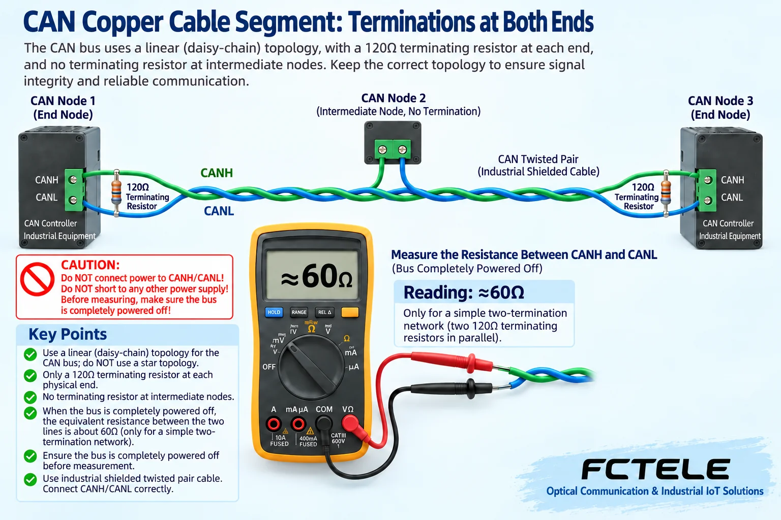
A simple linear electrical segment of high-speed CAN usually has one termination resistor matching the cable at each physical end, typically 120Ω, and intermediate nodes do not add more at will. If the converter is at the end of that segment, its built-in termination may need to be connected; if it is in the middle, check whether it should be disabled. Optical fiber does not connect the electrical wires on both sides into the same segment, so how each side is terminated must be confirmed separately based on the actual structure. Keep stubs as short as possible; the allowed length depends on edges, rate, and devices, and a certain “three-meter” number cannot be applied to all networks.
Use termination measurement to understand loading, do not mechanically pursue a single reading
Resistance matching is equivalent to reducing signal reflection at the cable end, making it easier for the receiver to determine the bit state at the specified moment. After all relevant devices are safely powered off and no external voltage is confirmed, in a simple network two 120Ω resistors in parallel measure about 60Ω between CANH and CANL, which can serve as a check clue. It is not a required indicator for any CAN network; split termination, protection circuits, built-in switches, and other connections may all affect the measurement, so you need to understand the structure first.
A measurement of about 120Ω may mean one end termination is missing, or it may be separated into a local network by a broken wire; a lower reading may mean extra termination or a short circuit. Normal resistance also cannot prove that wire order, common-mode range, and sampling point are all correct. Save the measurement location and connection status, then locate the problem together with message errors. Do not use the resistance range on a live network, and do not keep adding resistors just to reach 60Ω. For disconnection and power-off checks on a production network, arrange a maintenance window.
Optical path pairing and parameter settings should be checked separately
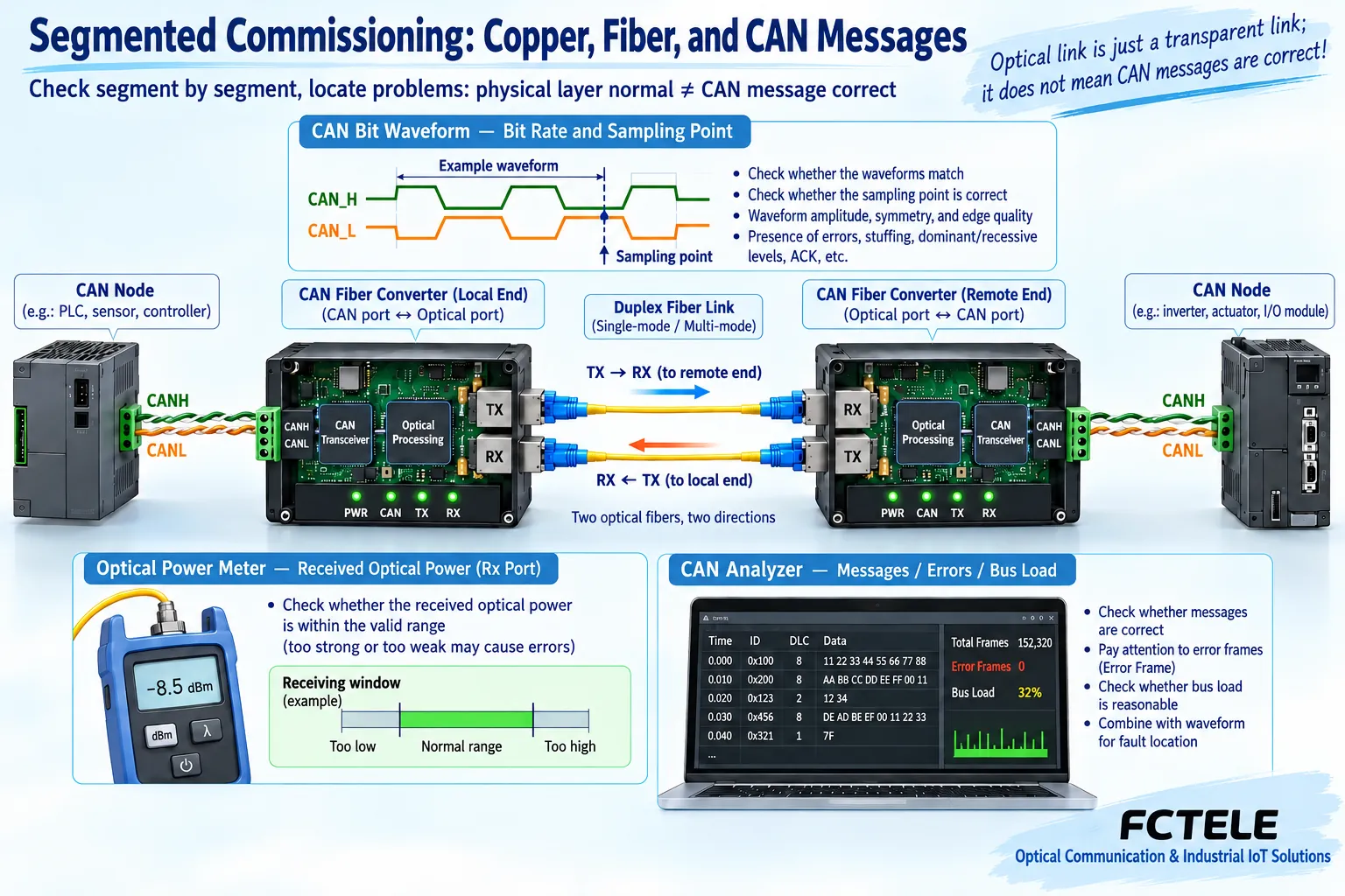
In dual-fiber connection, the local TX connects to the remote RX, and the other fiber completes the opposite direction; for single-fiber bidirectional, check the complementary transmit and receive wavelengths and the matching port combination. Single-mode or multimode, interface endface, wavelength, module support range, and received power window all need to be consistent. The nominal kilometer rating does not replace an optical loss budget, and when using a long-distance optical port over a short distance, you also need to check for receiver overload. Clean the endface and maintain a reasonable bend radius; do not look directly into the optical port or use your eyes to confirm light emission.
Nodes in the same electrical CAN segment should use compatible rates and bit timing. Baud rate means bits per second, and the sampling point is the moment within a bit when the receiver reads the state; matching only the rate may not provide enough propagation and synchronization margin. A transparent repeater is still subject to the timing constraints of the whole network. A bridge may support independent rates on both sides, but there must be a corresponding mode basis. “Automatic adaptation” also has implementation conditions, and you cannot infer that the device supports any rate or CAN FD.
Configuration software and DIP switches should only be used according to the corresponding version
For configurable models, first read back and save the original parameters, then confirm that the software, hardware, and firmware versions match, write after modification, and read back again. If the device has two sets of CAN fields, check whether they actually represent two independent electrical ports, internal transmission parameters, or other channels; do not guess based on field names. BTR is the bit timing register of some controllers, and its value is related to the clock and register definitions; the calculation result for one model cannot be directly copied to another model.
USB may only be a configuration interface, and whether it can power the entire device is determined by the manual; you also cannot assume that all CAN optical modems can be configured via USB. The rules for DIP switches, taking effect on power-up, or taking effect during operation also vary by model. Products that require no configuration do not need you to look for a menu that does not exist, and do not open the housing to look for switches. The Feichang FCP-C1 detail page lists a single CAN interface, one optical port, and transparent transmission, which can serve as a check entry point for a simple point-to-point solution; the industrial FCM-C1/2 page has different specification statements, and procurement and commissioning should obtain confirmation documents for the corresponding delivered version, not treat mixed parameters as a unified promise.
Light is on but communication fails: troubleshoot step by step in three segments
First confirm power supply and working status, then use a known-good short cable and a small number of nodes to verify the local CAN segment; next verify the optical path, and finally connect the remote CAN segment. The color and meaning of lights should only be interpreted according to the corresponding manual: an optical light being on may only indicate physical link status, and a CAN light blinking may only indicate activity; neither proves that application messages are correct. Change only one condition at a time, for example replacing one optical patch cord, disabling extra termination, or restoring a saved configuration, and record the result.
Use a CAN analysis tool to view messages, error counters, and controller status. Lack of acknowledgment, wrong rate, disconnection, or interference may cause retransmission; in severe cases, a node may enter bus-off state and stop normal transmission, and the recovery rule depends on the controller and software. If the analyzer is in listen-only mode, it may not provide acknowledgment, so you cannot prove complete communication with only a single transmitting node plus a listening analyzer. CRC is used to detect errors, and it cannot be called automatic repair of arbitrary messages by the optical modem.
From being able to communicate to being able to deliver, load and recovery acceptance are still missing
Assume there are several CAN nodes in each of two cabinets, and they can all send and receive over a short link at low load, but after connecting the site optical path, application timeouts occur at high load. Compare propagation delay, configuration on both sides, bus occupancy, and message priority to confirm whether there is buffer backlog or frequent retransmission; you cannot assume there is no capacity problem just because fiber bandwidth is large. Moving the device back to the short link for retesting can help distinguish the effect of the long optical path from parameter and load problems. This scenario is a commissioning example, not an actual customer case.
Delivery testing should cover representative bidirectional messages, competition among multiple nodes, continuous load, application response time, and the agreed fault recovery. Perform operations such as fiber breakage and power loss within a permitted maintenance window, and record alarms and the process of resuming communication; safety control should not rely on unverified automatic recovery. Maintenance records should retain model, software version, wiring, termination location, optical power, configuration files, and test results. Check heat dissipation, terminal tightening, and protection according to the complete manual; electromagnetic coupling resistance of the optical fiber segment does not mean the power supply and copper segment are exempt from surge protection.
Documentation note: The principle diagrams have been checked against technical content and are used to explain general mechanisms; they are not product photos or measured records. Specific interfaces, modes, and capabilities are subject to the selected model, version, and on-site verification.
Verification materials: TI: CAN physical layer and wiring requirements
TI: TCAN1042 transceiver documentation
Feichang FCP-C1 single-channel CAN optical modem
Feichang FCM-C1/2 product page
Translated from the Chinese technical article. Source first published: 2021-04-07. Source last revised: 2026-10-13T13:46:37+08:00. Read the Chinese source
