


A four-port RS-485 hub is suitable for splitting instruments or control devices into several independent wiring directions, but “four ports” does not mean four sets of unrelated serial services. When selecting a model, first confirm the number of downstream ports and the upstream interface, then check independent driving, isolation structure, direction switching, and on-site wiring. Only then can you avoid buying a device whose ports look sufficient but whose actual connection method is unsuitable.
How should the parameters of an isolated RS485 repeater be checked?
An isolated two-port repeater and an isolated multi-port hub may use similar isolated power supplies, signal coupling, and RS485 re-driving principles, but their purposes and port counts are not exactly the same. When you only need to separate the two sections before and after a bus, you can check a two-port repeater solution; when you need four wiring directions, then check a multi-port hub. The selection table should separately record the upstream and downstream interfaces, the signal and power isolation boundaries, and the direction switching and recovery behavior.
Isolation withstand voltage, ESD, surge, and temperature range are indicators under different test conditions. The 2500Vrms, 600W, ±15kV, or -40°C to 85°C from older articles cannot be directly applied to any model. Transmission distance and rate also depend on the cable, node load, termination, and on-site noise; 1500 meters or 5000 meters are not universal guarantees either. Transparent forwarding does not prove that all Modbus or Profibus devices can interoperate; you need to check the physical interface, serial format, protocol timing, and the requirements of the corresponding devices. Isolation reduces the risk caused by potential differences across network segments, but it does not replace grounding, lightning protection, or system safety measures.
1. First write clearly which lines the project needs to be divided into
The cable directions from the control cabinet to the four areas, the number of nodes at each location, the bus protocol, and the allowed refresh time explain the requirements better than a sentence saying “we need a four-port hub.” If the four areas use the same master station, the same serial format, and respond in sequence, transparent expansion can be considered. If the four ports are required to run at different baud rates simultaneously and connect to master stations with different protocols separately, then you need to confirm whether a multi-serial-port device should actually be used instead of an ordinary HUB with one branch.
Also distinguish between one upstream plus four downstream and four total ports. Some names are based on the number of downstream ports, while some materials describe the total number of ports. During procurement, you should request a terminal diagram and a function table for upstream and downstream. The upstream may be RS-485, or it may optionally be RS-232 or RS-422; the terminals, levels, and two-wire or four-wire methods cannot be interchanged. If the computer only has USB, the correct interface conversion conditions are also needed.
2. Why are four independent drivers valuable?
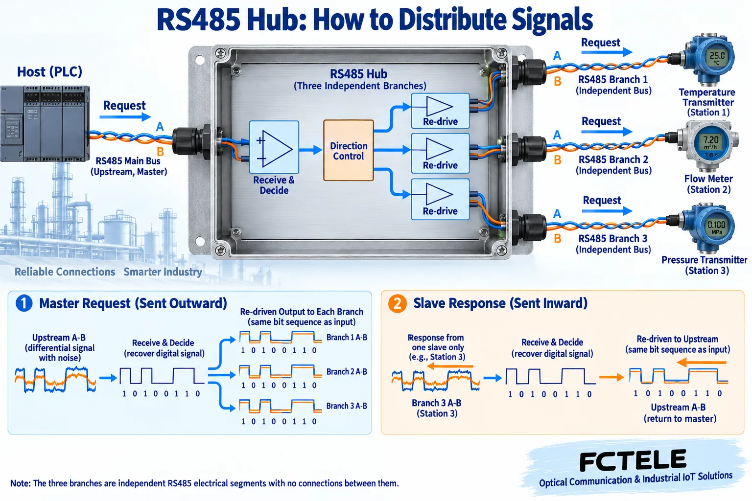
Passive splitting only connects conductors together; all device loads and branches still fall on the same electrical network segment. An active hub receives and decides the signal on the input side, and then the downstream drivers send it separately to different lines, allowing the wiring to be segmented by area. The direction logic inside the device switches between request and response, so the same set of serial data can reach multiple areas, and the response of the addressed slave can be sent back to the master station.
This mechanism does not create additional data channels out of thin air. When the master station sends one request, multiple branches may all see the request, and only the slave that matches the address condition can respond. The fact that four lines each have a driver does not mean that four devices can send to one upstream port at the same time; protocol scheduling is still important. For devices in the same polling network, you need to check whether addresses are duplicated, rather than renumbering separately from the same address on each branch.
3. Isolation depends on the specific boundary
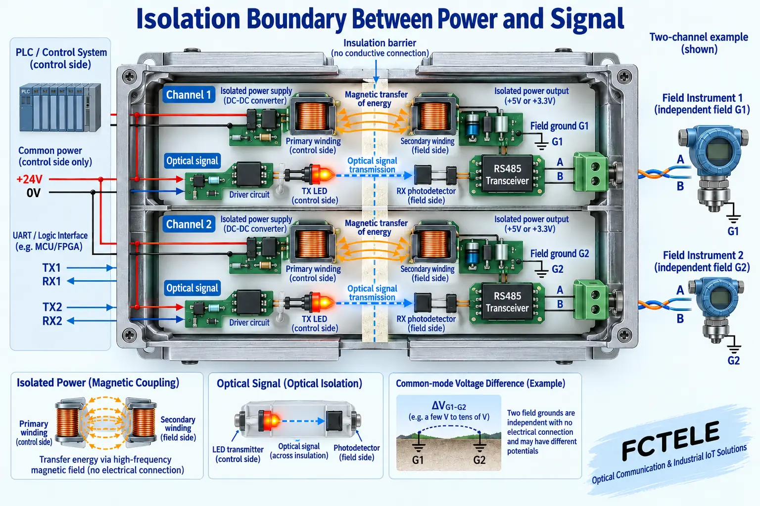
When connecting across floors or across cabinets, there may be a potential difference between the reference grounds of the two areas. An isolation structure transfers signals between the control side and the field side through non-conductive coupling, and an isolated power supply powers the field-side circuit. The purpose is to reduce direct conductive coupling. A structure with only an optocoupler while the field power ground is still connected is not equivalent to a structure in which both signal and power supply are separated.
When requesting a quote, confirm item by item whether the upstream and downstream are isolated, whether the downstream ports are isolated from each other, whether each branch shares the field ground, and how the shield ground terminal is connected. The isolation voltage needs to correspond to test conditions and boundaries, and cannot be used as the allowed input voltage of the terminal. Ordinary electrical isolation does not necessarily include fault detection either. Whether A/B short circuits can be identified, whether forwarding on an abnormal branch can be stopped, and whether a prompt can be given should all be checked separately in the model documentation.
4. Distance, rate, and node count cannot be promised separately
The longer the line and the faster the edge, the more attention should be paid to attenuation, reflection, and noise conditions; the maximum baud rate and maximum distance marked on a device may correspond to completely different test conditions. Do not directly apply the “long distance” number of another device, and even less should you treat the rate achievable by the interface standard as a promise of this product. You need to check the applicable range of the selected model under the specified rate, cable, load, and termination conditions.
The node count depends on the driving capability and the unit load of the receiver, and is also related to the actual line distribution. Standard nodes and enhanced nodes in the manual are not two kinds of protocol address capacity; you cannot judge how many more devices can be carried just by counting terminals. The procurement table should preferably record the existing nodes of each branch, planned expansion, cable length, communication format, and power supply location at the same time, so that during expansion you can judge whether the electrical load or time budget is being approached.
5. The four areas should each be wired as a bus
Assume a building project divides instruments on different floors into four branches. Each branch still connects instruments along a continuous trunk, node branches are as short as possible, and termination matching is arranged according to the physical end of each section. The hub is the location of active segmentation, and it does not permit long random star branches to continue at the far end. The construction drawing should specify terminal functions, shield handling, and reference conductors, rather than just drawing one green line to represent all wiring.
Communication cables and power cables should be laid separately, and protection and grounding solutions that meet engineering conditions should be used where they pass through cabinets or cross areas. A shielded cable cannot directly replace a communication reference line, nor should the grounds of different isolated branches all be shorted together for convenience. Whether to ground, at which locations to connect, and whether external surge protection is needed should be combined with the on-site electrical design and equipment manual, rather than uniformly applying “connect the shield at both ends” or “always connect only one end.”
6. Write product evidence and unconfirmed conditions separately
The Feichang Technology FCC-D4JM product page corresponds to an intelligent isolated hub with one master and four slaves. It lists four downstream and one upstream isolated interfaces, isolation after short-circuit and abnormal data detection, and DIN-rail mounting. It is suitable for one master station to segment in several directions, and treats fault handling as a selection condition. The product documentation also notes that terminal resistors are built in, so before construction you should check the actual version and internal termination conditions, and you must not add resistors repeatedly according to a general diagram.
In addition, the Feichang Technology FCC-D4M is a buffered four-master one-slave product. It provides configuration software and communication mode settings, and addresses the problem of multiple master stations accessing and buffer scheduling. Four-master one-slave cannot be directly treated as the same product as ordinary one-master four-slave; even if multi-master access is supported, serial communication on the slave side still requires device coordination. Having the supplier confirm upstream and downstream roles, isolation, power supply, environment, and mode according to the same requirements table makes acceptance easier than only accepting “industrial grade, plug and play.”
7. Verify procurement results with branch-by-branch testing
First connect a known-good slave on the bench and verify that the upstream and each downstream can transmit correct messages. Then gradually load real nodes by area and observe the success rate, checksum errors, timeouts, and the complete polling cycle. For automatic direction switching, service scenarios with short responses and longer responses should be included; testing one successful register read cannot show that all polling loads are stable.
Formal delivery should also preserve terminal photos, model versions, serial settings, address tables, and cable and termination locations. If other areas recover after one branch is disconnected, first check the wiring, nodes, and parameters of that area, and do not directly conclude that the entire hub is damaged. The goal of a four-port solution is to make wiring, expansion, and maintenance boundaries clear; actual reliability comes from a suitable product, correct construction, and reviewable test records.
Sources: Feichang Technology RS485 hub product category;Feichang Technology FCC-D4JM four-port product description;Feichang Technology FCC-D4M buffered multi-master product description;Feichang Technology FCC-D8J eight-port specification;Feichang Technology FC-D8JM intelligent eight-port product description;TI RS485 Design Guide;Modbus Serial Line specification entry. The schematic diagrams are general principle illustrations and belong to general mechanism illustrations; they are not actual PCBs, physical products, measured waveforms, or certification documents. Model capabilities are subject to the corresponding documentation and delivered version.
Translated from the Chinese technical article. Source first published: 2024-10-24. Source last revised: 2026-10-13T12:16:42+08:00. Read the Chinese source
