


Remote peripheral access: first determine the host
For example, a control room has an industrial computer, and a workshop has an industrial camera that supports USB connection. The goal is for the computer to obtain camera images. In this case, the USB fiber optic extender extends the connection from the computer to the camera. Image acquisition, device commands, and application decisions are still completed by the corresponding host and peripheral. The extender does not become a control server or automation protocol gateway just because of its name.
First draw the source device and the receiving device, and clearly mark the USB host role on the computer side. Two ordinary computers are usually both hosts, and a conventional USB fiber optic extender cannot be used to directly connect two host ports at will. Remote desktop applications control a computer over a network, which is not the same solution as directly extending a remote USB peripheral. If both are needed at the same time, list the network and peripheral paths separately.
The fiber optic extender solves the middle extension segment
A common connection is: the computer USB port connects to the host-side device, then through a matched optical link to the remote device, and then a short USB cable connects to the peripheral. Both host requests and peripheral responses must be transmitted along supported mechanisms, and the USB device still needs to be correctly recognized and configured. The bidirectional path in the diagram represents the communication relationship. It cannot be used to describe a USB2.0 copper port as capable of full-duplex transmission in both directions at the same time.
The optical port of a dedicated fiber optic extender does not automatically interoperate with ordinary Ethernet switches or other brands’ optical devices. The fiber type, optical port pairing, and link loss must match the specific version. A dual-fiber example must correctly cross transmit and receive. When using a single-fiber solution, connect according to the matching wavelength and model, and do not mix the jumper methods of the two solutions. Optical cable connection and normal USB transactions still need to be verified separately.
Check the power at both ends and the remote load separately
Fiber optics do not directly deliver power from the host USB port to the remote end, so the optical devices at both ends and the peripherals need to meet power supply conditions separately. The remote port power capability, the total load of multiple peripherals, inrush current, and the external power connection method must all be confirmed. You cannot see one fiber optic cable and then skip remote power planning, nor can you reverse-connect two power supplies according to an unconfirmed port.
During installation, leave maintenance space for short USB cables, pigtails, and power connectors, and avoid pulling and exceeding allowed bending conditions. Device temperature, heat dissipation, and protection are based on the actual model. Using fiber optics cannot replace engineering measures for cabinets, power protection, and copper ports at both ends. When the field load is complex, keep allowed power measurement records rather than only recording the number of peripherals.
Industrial acquisition is not equal to safety control
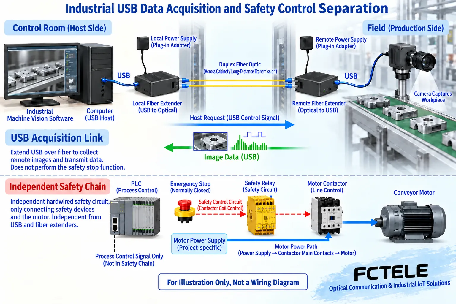
Industrial cameras, barcode devices, or measuring instruments connected via USB can be used for acquisition, identification, or maintenance. Whether they support the target application must be verified according to the actual device. A PLC’s USB port may be used only for programming or maintenance and cannot be directly treated as a cyclic control network. Serial, CAN, or Ethernet devices will not automatically interoperate with a computer application just because a USB fiber optic extender is added in the middle.
Safety chains for emergency stops, door interlock, or dangerous actions need to be designed according to the project’s independent control and safety requirements. Ordinary USB peripheral extension cannot be described as a safety-certified link, nor can deterministic control cycles be inferred from smooth video. In the diagram, the USB camera is responsible for acquisition, and independent safety devices handle the corresponding tasks. This is a hypothetical scenario to explain the division of roles, not an unverified customer case.
Software must know whether data is still updating
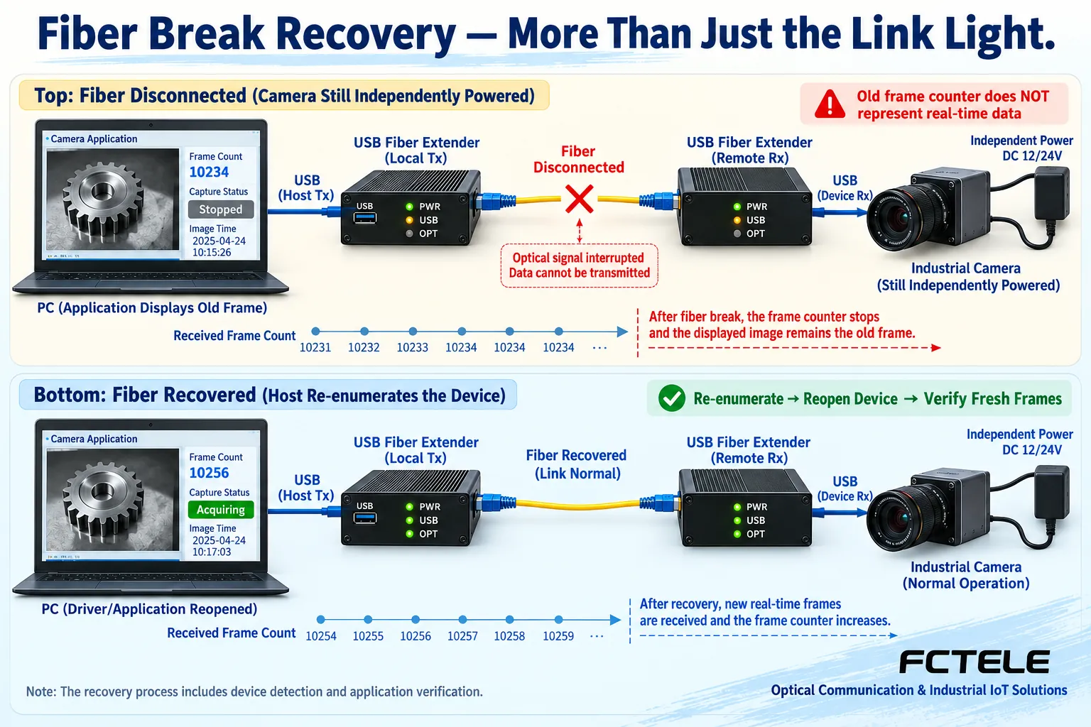
After device recognition is complete, the driver and application need to open the correct interface and obtain new data. When the camera image stops at the last frame, the window may still show an image, but that does not mean the site is still updating in real time. Data freshness should be checked through actual frame numbers, time, business counters, or available status. The specific mechanism depends on the device and application, rather than assuming every extender outputs a valid bit.
The extender itself does not need a dedicated driver, which does not mean the camera or instrument does not need a driver. Error handling, device reopening, and permissions in the application also affect recovery. When deploying across host systems, verify the corresponding software combination. Fiber optics cannot automatically provide encryption and user authentication. Sensitive peripherals also require clear host access permissions and the actual implementation of required security functions.
Fiber break recovery must follow the complete business process
After the optical path is interrupted, the peripheral may disappear, the application may report an error, or it may remain in an old state. The specific behavior depends on the implementation. Recovery of the optical light only proves the corresponding optical state. USB status and application resources may still need to be re-established. Check whether the host re-recognizes the device, whether the driver works, whether the application reopens the interface, and whether the first set of new valid business data arrives.
Maintenance testing must also cover host restart, sleep wake-up, transmitter power loss, receiver power loss, and allowed hot plugging, and record the recovery method item by item. You cannot broadly promise automatic recovery after a fiber break, nor use repeated plugging and unplugging as a long-term maintenance strategy. All exception drills should be arranged under allowed maintenance conditions to avoid testing unknown device states with real production actions.
Put Feichang Technology product features into the requirements table
Feichang Technology FCP-UT/FCP-UR documentation describes USB2.0 host interface fiber optic extension and remote four-port expansion, suitable for starting verification from a candidate structure of one host and multiple peripherals. For industrial image acquisition, require confirmation of camera model, data mode, shared bandwidth, and peripheral power, rather than confirming all industrial cameras are usable just because the list includes the word camera.
This series documentation lists power options. When actually ordering, specify power supply, installation method, and matching version. Some distance fields on the official website differ from historical articles, so cross-workshop lines need to be judged according to confirmed optical parameters and USB service testing. The article does not expand commercial models into all industrial temperature capabilities, nor does it promise to reduce downtime ratios or unconditionally guarantee production safety.
Commission in stages and deliver reproducible records
First connect the actual peripheral directly to the host and verify the driver and application. Then use matching equipment with a short fiber, and finally connect the installed optical cable. If adding other peripherals, add them one by one and then run them simultaneously, recording resources and exceptions. When troubleshooting, change one condition at a time and keep a known-good baseline, so you can distinguish the responsibilities of the optical path, USB connection, power, host software, and application processing.
Delivery should include host and peripheral identities, port roles, optical device versions, optical cable and power supply, business settings, combined operation, and recovery results. The recipient should be able to reconnect the original system according to the diagram and know how to verify new data after a fiber break or power loss. The value of a remote USB solution is maintainable extension on a clear interface. Whether it meets production needs is ultimately proven by actual tasks and measurement results.
Documentation note: The principle diagrams have been checked for technical content and are used to explain general mechanisms. They are not product photos or measurement records. Specific interfaces, modes, and capabilities are subject to the selected model, version, and field verification.
Verification materials: Feichang Technology FCP-UT/FCP-UR USB2.0 fiber optic extender details
Feichang Technology FCP-UT/FCP-UR USB2.0 specification sheet
USB-IF USB2.0 specification resource entry
Microsoft: USB bandwidth allocation and transfer types
Related technical topics: How to evaluate USB fiber optic extender speed and latency: shared bandwidth, transfer types, and measured acceptance How to judge USB fiber optic extender compatibility: host enumeration, endpoint types, and peripheral drivers How to choose a USB2.0 fiber optic extender: four-port expansion, shared bandwidth, and power budget How to plan conference room video fiber optic extenders: verify HDMI display, USB capture, and IP conferencing separately
Translated from the Chinese technical article. Source first published: 2024-11-20. Source last revised: 2026-10-13T11:52:05+08:00. Read the Chinese source
