


Industrial Ethernet switches and industrial EPON can both carry Ethernet services, but the way optical fibers are connected and access is scheduled differs. Switches commonly use independent ports to connect each link segment; EPON connects one PON optical port through a passive optical splitter to multiple optical network units. When choosing, first look at node distribution, power supply, and services, then check shared bandwidth, fault scope, optical budget, and management capabilities. Do not replace on-site verification with the words “industrial grade.”
1. A switch’s optical port and a PON port are not the same interface
A switch receives Ethernet frames and selects an output port based on MAC addresses, VLANs, and corresponding rules. A normal optical Ethernet link usually connects matching transceiver interfaces at both ends; multiple terminals require more ports or a downstream switch. An optical port is only responsible for transmitting and receiving on the corresponding medium; it does not automatically provide PON terminal registration and shared link control.
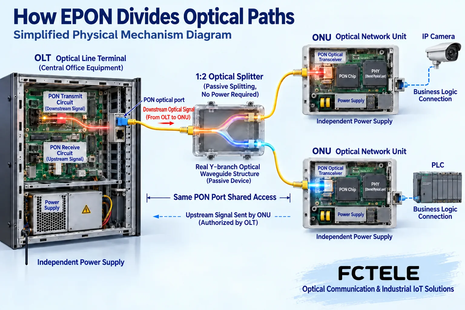
In EPON, the OLT is the central office equipment, and the ONU is the on-site access end. The OLT’s PON port connects through optical fiber and a passive optical splitter to multiple ONUs, and terminals then connect to the ONU’s electrical ports. The splitter only distributes optical power; it does not learn MAC addresses, does not schedule data, and does not need on-site power. The OLT and ONU still need power. Therefore, “passive optical network” does not mean the entire network continues working after a power outage.
Similar interface appearance and both using single-mode fiber do not prove that a regular switch SFP can replace a PON module or ONU. EPON and GPON also have different protocol systems; compatibility modes, terminal authentication, and management capabilities should be verified according to both parties’ models. Parameters from one type of OLT documentation cannot be moved to another device, and “the optical port is connected” must not be treated as completed service access.
2. Why multiple ONUs cannot all transmit together at any time
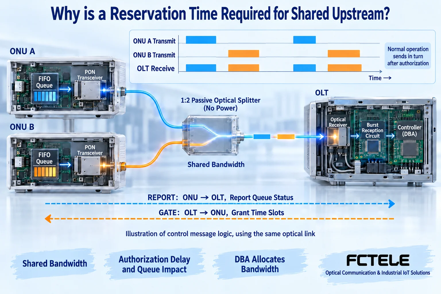
Multiple ONUs on the same PON port share the upstream optical channel to the OLT. To avoid normal service transmissions overlapping each other, the OLT arranges each ONU’s transmission time slots through control messages; ONUs report queue requirements, and the OLT uses this to implement corresponding bandwidth allocation. Here DBA means dynamic bandwidth allocation; specific policies and service guarantees need to be verified according to device configuration and implementation.
You can think of time slots as reserved speaking turns, but this is only an analogy to explain the sharing relationship and is not used to calculate precise latency. Queuing, authorization waiting, and actual load all affect service experience; a terminal electrical port labeled gigabit does not mean every ONU simultaneously has exclusive gigabit PON capacity. Downstream reception, logical link identification, and security configuration also need to be correct, and the shared medium must not be mistaken for all terminals being able to arbitrarily access each other’s data.
Although each access port of a regular switch has its own link, multiple data streams may still converge to the same output and queue, so it is not naturally congestion-free either. Both solutions must check the uplink, burst traffic, and effective application throughput. When fixed-period control is required, clear load, latency, and jitter indicators should be specified; deterministic response or zero packet loss cannot be inferred from the protocol name.
3. Splitting and distance must be placed in the same budget
Adding branches distributes optical power, and connectors, optical cables, and splices also have losses. Before expansion, check the module’s transmit and receive windows, splitter loss, farthest and nearest branches, and maintenance margin. Do not simply replace with a splitter with more ports without rechecking the optical budget. Being able to register and come online does not mean there is still sufficient margin after contamination, temperature changes, or long-term aging.
Older articles limited EPON to always 20 kilometers and described switches as fixed at up to 100 kilometers; this is not a procurement rule that can be directly applied. Actual distance is related to the selected optical interface, protocol configuration, fiber type, and link conditions; a longer-distance module also does not mean a short link is necessarily safe. Power and loss need to be measured and judged according to receive sensitivity and overload boundaries, rather than staring into the optical port or bending the fiber to try to dim it.
Ordinary optical switches can also use matching bidirectional single-fiber modules. Saving fiber cores is not an advantage unique to EPON; EPON’s key difference lies in its point-to-multipoint shared access and management mechanism. Both solutions should keep records of fiber cores, end faces, device ports, and spare resources. A single service fiber core also does not mean the project only needs to prepare one fiber core.
4. Fault scope cannot be summarized by saying which is more reliable
In EPON, an interruption in one branch usually first affects the corresponding access end, but a fault in the trunk, splitter, OLT, or their power supply may affect multiple branches. Abnormal ONU behavior may also affect the shared channel; whether detection and isolation are supported should be verified by model. How services are forwarded and isolated between ONUs also depends on the OLT and network configuration. Devices under the same splitter cannot be assumed to naturally communicate with each other without the OLT.
In a switch network, the impact of a single point depends on the topology and service paths. A star core failure may affect a large area; power loss to an intermediate cascaded device may cut off downstream devices; a ring connection without correct loop prevention control may also cause a broadcast storm. Backup lines, dual power supplies, and recovery protocols solve different problems. Do not declare high reliability based on port count or connection shape.
Industrial applicability should be checked item by item against temperature, heat dissipation, power supply, installation, protection, and electromagnetic compatibility documentation. The general conclusions that “EPON is newer so it is not industrial enough” or “industrial switches fully satisfy all environments” should not continue to be used. Under the same name there are different models and versions; on-site conditions and maintainability are the basis for comparison.
5. Turn FCTEL product options into acceptable requirements
The FCTEL FCX-9001 product entry lists eight EPON downstream ports, as well as gigabit electrical and 10-gigabit optical uplinks, and describes ONU authentication, DBA, and PON management functions. The FCX-8001 entry provides four gigabit electrical ports and one PON access port; PoE is an optional configuration. This information helps distinguish the roles of central office, access end, and terminal power supply. It does not mean every electrical port has exclusive PON bandwidth, and optional power supply must not be written as standard on all models.
Some protocols, wavelengths, and splitting parameters are mixed together in the official website’s PON materials. When ordering, they need to be clarified using the formal specifications and module list for the corresponding protocol version. The plan should specify the OLT, ONU, firmware, authentication method, splitter configuration, optical budget, service bandwidth, and fault recovery targets; do not piece together a seemingly complete set of definite parameters when the materials are ambiguous.
6. Acceptance must look at the optical path, management, and real services at the same time
First safely check power supply and wiring, then record optical power and terminal registration status segment by segment; afterward check VLANs, multicast, rate limiting, and permissions, and run actual control and monitoring services. Observe throughput, latency, jitter, and errors when all access ends are busy at the same time, rather than only testing a single idle port. Backup path testing should be authorized and have a rollback plan.
Keep equipment lists, branch relationships, port configurations, and measurement baselines. During a fault, first distinguish whether one terminal is offline or multiple branches are abnormal together, then check the common optical path, power supply, and central office alarms. Back up configurations before remote changes to avoid damaging the entire PON port while trying to restore one ONU; dangerous voltage work must be performed by qualified personnel.
Sources: RFC 4837 EPON architecture and management mechanisms ; IEEE 802.3ah project materials ; FCTEL FCX-9001 ; FCTEL FCX-8001 . The images are general mechanism illustrations, not product photos or on-site test evidence.
Translated from the Chinese technical article. Source first published: 2019-09-10. Source last revised: 2026-10-13T11:23:08+08:00. Read the Chinese source
