


Start with the conclusion
An isolator solves conductive relationships; it does not automatically translate protocols
DP copper lines between different cabinets may face ground potential differences and interference. A suitable bus isolator or repeater device can segment the line, receive the signal on one side, re-drive it on the other side, and separate part of the conductive path as designed. It still needs to maintain the corresponding DP communication conditions. Just because it is called a protocol-type device does not automatically make it a Modbus or Ethernet gateway.
When choosing, first look at what actually needs to be isolated, which segment is being changed, and what speed and delay are required. Ordinary RS485 converters, electrical port isolators, and DP fiber optic repeaters cannot be substituted for one another based on appearance alone. This article explains general electrical mechanisms. Unverified whole-device isolation withstand voltage, power supply, and protection figures are not treated as parameters for all products.
Differential transceivers and isolators each complete one step
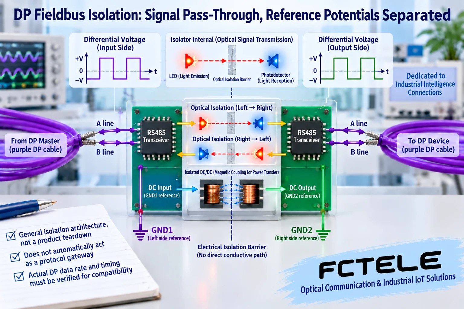
The RS485 receiver on the left identifies the voltage difference across the wire pair and hands it to internal logic. The isolator transfers the required state to the other side, and the corresponding driver then establishes the electrical signal for the right-side segment. An optocoupler can use an internal short optical path to transfer logic. Other designs may use magnetic or capacitive coupling. The specific implementation depends on the component and device.
This is not an external fiber optic transmission line. The distance, energy, and interface conditions of the internal isolation element are also not the same as an optical modem. DP’s transmission direction, speed, and timing need to be met by a suitable implementation. You cannot assert that a complete device meets the service just because a chip can transfer logic. A teaching cutaway does not represent the actual PCB of a specific model.
Beyond signal isolation, also check power supply and reference
The signal does not directly conduct between the two sides, but if the power supply reference is externally bridged, it may bypass the intended isolation. An isolated DC/DC transfers power energy through mechanisms such as magnetic fields, which is a different role from signal isolation. How the references on both sides connect to their respective electrical segments, enclosures, and protection should be checked according to the complete device and site design.
Isolation withstand voltage, permitted working potential, surge, and electrostatic tests belong to different conditions. A single high-voltage number cannot replace all protection. You also must not apply high voltage to a running bus or create faults just to test isolation. Appropriate documentation and controlled verification are what make sense. Replacing the middle conductive path with fiber does not remove the need for endpoint power and copper port protection.
After segmentation, each segment still needs correct termination
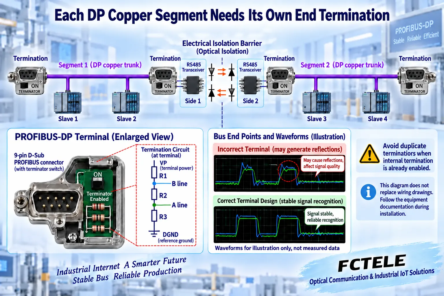
The two sides of an isolator or repeater can form different copper network segments. Determine the two terminations and terminators separately according to the actual topology. A common PROFIBUS-DP terminator is a combination of bias and matching resistors and requires the corresponding power supply. You cannot simply copy an ordinary RS485 single terminating resistor, and you should not unconditionally enable termination at every slave.
If built-in termination already exists, confirm whether it is enabled. An external connector switch may also cut off the outgoing line. If the end device loses power, the termination may lose its power supply. These conditions must be checked during both installation and maintenance. The presence of an isolator between two segments does not mean the original termination can be kept arbitrarily or all removed.
Why long star branches are not encouraged
Branches and mismatched terminations on a copper transmission line can produce reflections. Reflections add to the original waveform and affect the receiver’s judgment at the correct moment. The higher the speed, the tighter the time left for recognition. Line length, cable, connectors, and actual topology need to be evaluated together, not just the maximum distance marked on one device.
When multiple directions are needed, check dedicated active segmentation or distribution devices and their permitted structures, rather than arbitrarily tapping long branches from the same terminal. Device load, cascade count, and processing time also affect network design. Duplicate station addresses and incorrect master-slave configuration are not problems that electrical isolation can solve.
The name “protocol type” must be backed by compatibility evidence
Check whether it is explicitly applicable to the target PROFIBUS-DP speed, line transceiver conditions, and control system requirements, and whether there is documentation for modes, direction, diagnostics, and the corresponding version. Different speeds on the two sides will not naturally be compatible just because there is a buffer, and a continuous speed difference cannot be permanently absorbed by limited storage.
DP multi-master access cooperation and typical single-master polling have different conditions. An isolation device should not be treated as a master that redistributes transmission rights. If conversion to another application protocol is truly required, corresponding gateway functions and mapping documentation are needed. Electrical segmentation itself does not accomplish this work.
Choose electrical port isolation and fiber extension separately by actual model
A photo of a DP optical transceiver with optical interfaces cannot be used to prove an isolation version with only two electrical ports. In Feichang Technology’s current DP product categories, 788 and 1171 are fiber extension products. The latter lists two optical paths and corresponding topology uses. These materials cannot be used to prove the withstand voltage or port count of another two-electrical-port isolator.
For inquiries, provide the actual model and version and request the corresponding electrical ports, isolation structure, termination, speed, delay, power supply, environment, and installation basis. If optical transmission across buildings is needed, check DP optical transceivers separately. If the goal is only electrical segment isolation, do not use photos of products with optical ports as complete selection evidence.
First verify the source segment, then add the isolation device to the link
Use one known slave and a correct short copper cable to confirm the original DP baseline. Save the configuration, process data, and diagnostics. After power-off, check power supply, pins, reference, speed mode, and termination, then connect the isolation device. Then verify the two segments separately and the complete communication. Change one condition at a time; do not change address, speed, and wiring at the same time.
If there is no data, first check whether the master and slave were originally normal, and check electrical connections and mode. For intermittent abnormalities, then locate the issue together with termination power, topology, and load. Using an oscilloscope or analysis tool requires suitable probes and reference conditions to avoid instrument grounding bypassing isolation or causing a short circuit. A blinking light is not complete evidence that the response is correct.
Acceptance must cover representative load and recovery behavior
After the bench test passes, retest with the target cable, nodes, and service load. Record diagnostics, errors, communication cycles, and permitted power-loss recovery. When reading a value, also confirm it is new data from the target device. For execution-type services, check the actual feedback separately. Successful electrical isolation and successful application recovery should be recorded separately.
The handover document should clearly state the device model, the two electrical segments, termination switches and power supply, protocol configuration, permitted cascading, protection, and maintenance methods. Seeing two interfaces or one isolation element only shows part of the structure. Being able to stably complete real DP data tasks and explain fault location is what completes selection and segmentation handling.
Documentation note: The illustrations are general mechanism diagrams and have been technically checked. Appearance for marked models refers to official website photos. Other cutaways and components do not represent the internal circuits of real Feichang Technology products. They are not measured waveforms or real project sites. Wiring and power supply are subject to the delivery manual.
Verification materials: PI PROFIBUS Design Guide
PI PROFIBUS Termination and Connection Notes
TI RS485 Electrical and Differential Design
Feichang Technology Profibus-DP Optical Transceiver Categories
Feichang Technology Single-Channel Profibus-DP Optical Transceiver 788
Translated from the Chinese technical article. Source first published: 2021-05-20. Source last revised: 2026-10-13T10:45:04+08:00. Read the Chinese source
