


Conclusion First
First, the Actual Task: Send DP Traffic to Remote Devices
The master station inside the control cabinet needs to communicate with remote drives or distributed I/O. The long copper cable passes near motors or through different buildings. You can evaluate a Profibus-DP fiber optic repeater. It receives the DP electrical signal at the near end, transmits it over fiber to the far end, and then restores it to a line signal that the device can receive. What changes is the transmission medium, not the meaning of the control commands.
It is not a home broadband optical modem, nor an ordinary Ethernet switch. DP devices, ordinary RS485 instruments, and PROFINET networks have different communication conditions. You cannot mix them just because connectors or names look similar. Before use, first confirm that the connected service is indeed the corresponding PROFIBUS-DP version, target rate, and device role, then check the converter documentation.
In a DP Network, Protocol and Electrical Signals Have Separate Roles
PROFIBUS-DP is a fieldbus communication method. Common copper segments use RS485 differential transmission. Differential means the receiver mainly compares the voltage difference between the wire pair. Addresses, diagnostics, and process data are organized by the bus protocol. Similar RS485 electrical conditions do not mean that any serial optical modem meets the rate and timing required by DP.
In a common single-master scenario, the master exchanges slave data according to the communication schedule. When multiple masters exist, the right to send must also comply with the corresponding bus mechanism. An optical repeater does not become a new master just because it is connected to the network, nor is it responsible for correctly translating wrong device parameters, duplicate addresses, or incompatible services. The figure in this article uses a single-master task as a simplified example.
How Electricity Becomes Light, Then Becomes Electricity Again at the Far End
The near-end differential receiving circuit recognizes the copper wire input. The internal direction and signal organization circuit processes it according to the device design, then drives the optical transmitter. Light travels through a suitable glass fiber core. The far-end detector converts the arriving light changes into electrical signals. The recovery processing and RS485 driver then produce the DP copper segment output. Current does not pass through the glass; what is transmitted is the corresponding information.
Devices may use different encoding, direction recognition, or forwarding processing. You cannot assume there is no internal processing just because it is called transparent transmission. The enlarged figure only explains the general physical process; it is not a teardown of a Feichang actual unit. The reply also needs a corresponding reverse path. Dual fiber usually connects transmit to the opposite receive. Single fiber bidirectional pairs according to the corresponding optical configuration.
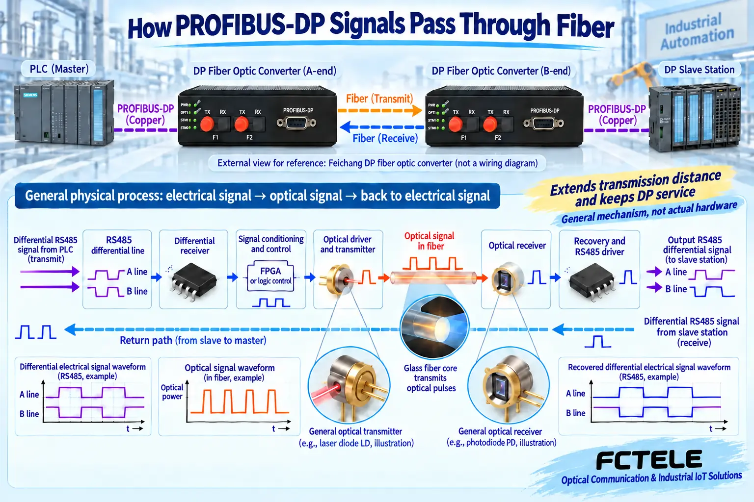
Fiber Improves the Middle Section, But Does Not Automatically Increase DP Rate
Glass fiber core does not rely on a conductive path to carry data. It is suitable for reducing electromagnetic coupling in the middle section and conductive paths across zones. However, the short copper cables at both ends, power supplies, enclosures, and metal components of the optical cable are still on site and must be handled separately. You cannot write medium characteristics as absolute lightning protection for the whole unit, no data loss in any environment, or all ports already isolated.
DP service still runs at the set rate. Longer lines have propagation time. Repeaters also have processing time. Terminal response and network scheduling also occupy the cycle. Higher fiber bandwidth does not mean the master refresh is necessarily faster. Timing parameters should be checked against the control system and product requirements. You cannot simply increase the kilometer number while ignoring waiting conditions.
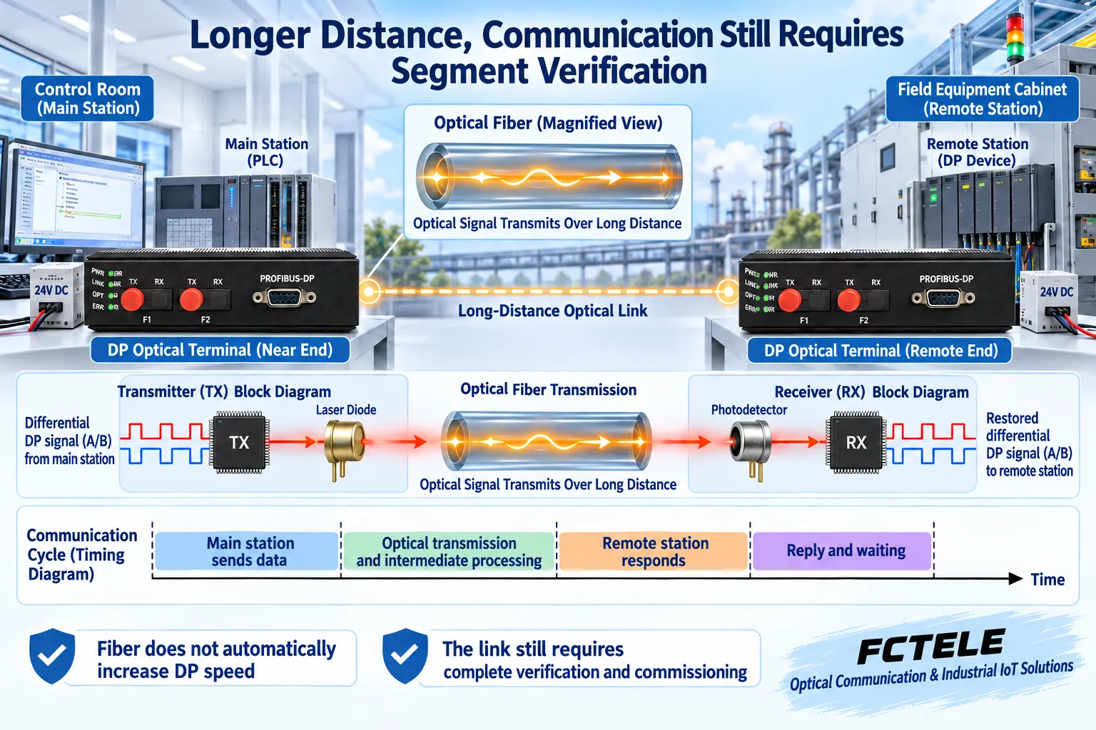
Each Electrical Segment at Both Ends Has Its Own Boundary, and Terminations Are Checked Separately
Fiber connects copper segments but does not cancel the wiring requirements of each segment. Determine the two physical ends, nodes, and branches of that segment, then check termination and power supply. PROFIBUS-DP termination usually includes a bias and matching resistor network. It is not suitable to simply copy a single resistor value from general RS485, and you must not enable termination at every node.
Some connectors also cut off their outgoing line when termination is turned on. Connecting the wrong cable entry may isolate the device from the network. When maintaining end devices, also confirm whether the termination power supply fails when the device loses power. Built-in termination, external termination, and connector switches should be confirmed item by item according to the manual to avoid duplicate stacking or omission.
Choose Point-to-Point, Chain, Star, and Ring Topologies Separately
Point-to-point is suitable for extending between two segments. Multi-node chain requires corresponding upstream and downstream optical ports. Star requires active optical distribution or compatible multi-direction devices. You cannot splice several fibers together as service aggregation. The actual port count and forwarding mechanism determine the topology. Having optical ports on the housing does not mean all structures can be connected arbitrarily.
Closing a ring also requires clearly supported redundancy modes and compatible devices. A physical ring is not automatic fault tolerance, and you cannot directly apply Ethernet STP or optical module settings from other manufacturers. The difference between dual bus, two electrical ports, and two optical ports is covered in a separate article in this group. Avoid mistaking port count for redundancy of the entire control system.
Feichang Single-Channel and Ring Versions: Check Details Separately
The Feichang 788 single-channel product documentation lists one DP service, optical version selection, and corresponding rate adaptation notes. The 1171 FC2P-P1G lists two optical paths, chain, and redundant ring topologies. Both are used for corresponding DP optical extension, but single-optical and dual-optical uses, ordering configurations, and compatible combinations cannot be mixed up.
The official website lists adaptation notes from 9.6 kbit/s to 12 Mbit/s. Specific functions are confirmed by the delivered model. Power supply and temperature statements in different parts of the webpage are not completely consistent. When requesting a quote, you should obtain the clear nameplate, specifications, and wiring documentation for the current order. Do not take the maximum range yourself, and do not treat fixed recovery millisecond values from old articles as unconditional promises.
Optical Configuration Depends on Pairing and Power, Not Just Whether the Interface Can Be Inserted
Single-mode, multi-mode, and plastic optical fiber require different optical components. They cannot be interchanged just because the connector form is the same. Single-fiber or dual-fiber, wavelength, end face, and transmit and receive ranges must all match. Ordinary Ethernet optical ports and DP dedicated transmission ports also cannot be directly connected just because the modules look similar.
The line has loss. Connectors, splices, bends, and contamination all affect margin. Evaluate the budget based on the corresponding transmit and receive specifications and line loss, then measure the formal optical path. Too strong reception can also exceed the range. When testing long-distance versions with short fibers, also check overload first. Use appropriate electronic tools to inspect end faces. Do not look directly into optical ports.
First Bench Short Link, Then Connect the Formal On-Site Optical Cable
First confirm that the original copper line baseline can communicate. Save the master configuration, slave parameters, and known normal data. Add the same pair of DP optical devices and suitable short fiber. Keep the master and termination settings. Verify bidirectional data and diagnostics. After passing, connect the formal optical cable. Record optical path conditions, errors, and cycles. Change only one condition at each step.
If short fiber also fails, first check model and rate mode, copper port, power supply, and optical pairing. If one direction is normal, check the response and reverse path. Do not directly conclude that the long optical cable is broken. A lit lamp only proves partial status. Cyclic exchange, actual input and output, and diagnostic data need to be confirmed separately.
Acceptance Looks at Continuous Service and Recovery After Abnormalities
Use representative device counts and loads to observe communication cycles, retries, and diagnostics. You cannot just test on an empty short line. Within the allowed maintenance window, verify disconnection, endpoint restart, and recovery. Distinguish three stages: optical path reconnection, DP data exchange restart, and application display update. Control actions also need independent feedback. You cannot infer execution completion from communication recovery.
Delivery should leave the ordered version, DP configuration, copper segment termination table, optical path numbers, power supply installation, baseline records, and exception handling methods. Maximum cascade count, recovery time, or compatible brands without clear product evidence should be written as to be verified. Only when later users can reproduce normal exchange and locate faults segment by segment does it prove that fiber extension suits this actual task.
Documentation Note: The figures are general mechanism diagrams and have been technically checked. The appearance of marked models refers to official website photos. Other cutaway views and components do not represent the internal circuits of Feichang actual products. They are not measured waveforms or real project sites. Wiring and power supply are subject to the delivery manual.
Verification Materials:Feichang Single-Channel Profibus-DP Optical Modem 788
Feichang FC2P-P1G Ring-Type DP Optical Modem 1171
PI PROFIBUS Design Guide
PI PROFIBUS Termination and Connection Notes
PI PROFIBUS Fiber Types and Interfaces
FOA Optical Link Loss Budget
Translated from the Chinese technical article. Source first published: 2021-04-13. Source last revised: 2026-10-13T10:45:04+08:00. Read the Chinese source
