


First confirm what the device is transmitting
When an extender shows smearing, color cast, black screen, or flicker, first confirm the input interface and the intermediate transmission method, then check the specific fault. VGA analog color signals, HDMI digital video, dedicated fiber links, and video-to-IP networks have different processing circuits and diagnostic entry points. They are all called extenders, but they cannot use the same set of knob adjustments or network port test methods.
Draw the path from source device, transmitter, line, receiver, to display, and record model, version, power, and current mode. For combinations with USB or keyboard/mouse, also record the peripheral services separately. A picture showing does not prove peripherals work, and a network light being on does not prove the display format is correct. After fixing these conditions, change one variable at a time to know which step produced the improvement.
Use direct connection and short link to divide the fault scope
First use a known-good short cable to directly connect the same source and display, and save a baseline of text, color bars, and dynamic picture. If the direct connection is already blurry, missing color, or black, first check the output, display input, and short cable. After the direct connection is normal, add the matching extender, correct power, and applicable short line, keep the video mode unchanged, and do not change the display and cable at the same time.
Only when the short link passes but the installed line fails should you focus on long-line loss, splicing, interference, and on-site power; if the short link also fails, continue checking pairing, direction, configuration, and compatibility range. A lower mode working is only a locating clue, and you cannot record the reduced test as the original target passing. Operate according to the manual and maintenance plan, do not try plugging unknown interfaces, and do not try connecting unknown power.
Why VGA smearing cannot be solved by amplification
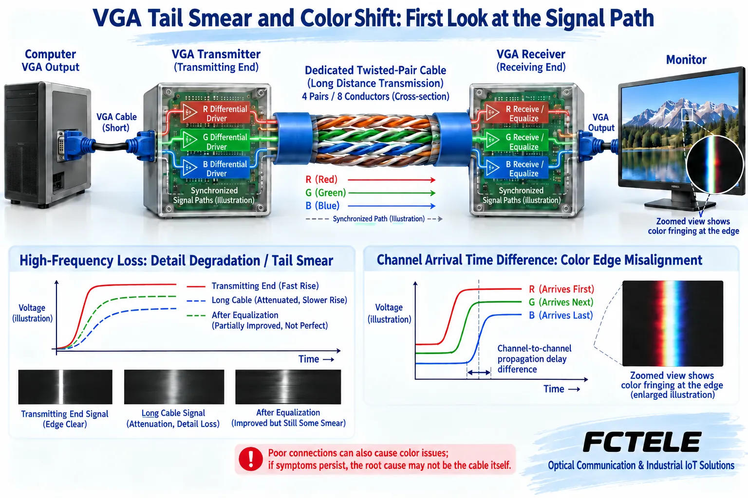
VGA red, green, and blue are analog color channels, and corresponding synchronization conditions are also needed. Devices that use twisted pair for analog extension transmit this information through applicable transmit and receive circuits. The line affects different frequencies differently; when the high-frequency components needed for detail weaken and edges become slower, the picture may look soft or show smearing. Connectors and impedance discontinuities may also cause reflections, so you cannot conclude that distance is too long just because you see smearing.
Some products provide gain or equalization adjustments: gain changes amplitude, and equalization compensates the frequency response accordingly. They do not mean any damage can be restored; excessive compensation may add noise or overshoot. Only when the model truly has the setting and you have obtained the operating method should you adjust in small steps on a fixed test pattern and record it. Do not randomly look for knobs based on old articles, and even less should you treat turning it to maximum as a universal repair.
Locate VGA missing color, color fringing, and stripes separately
Poor contact in one color path, or an abnormal cable or endpoint, may affect the overall color; if the three paths arrive at different times, color fringing may appear on thin lines or text edges. Amplitude, frequency response, and channel skew are different conditions. Use the same color bars and thin-line pattern to compare short and long cables, and replace with known-good cables or paired devices in the allowed way; you cannot determine the root cause from one photo.
For stripes and jitter, also record the time of occurrence, nearby equipment operation, power, and line status. Shielding, reference, and protective grounding should be implemented according to the equipment and site design. Do not remove protective ground to eliminate stripes, and do not directly claim that changing to shielded RJ45 plugs will solve all problems. Interface checks must follow power-off requirements; do not use wiggling a live plug as a formal diagnostic method.
Digital video checks the line and also the complete format
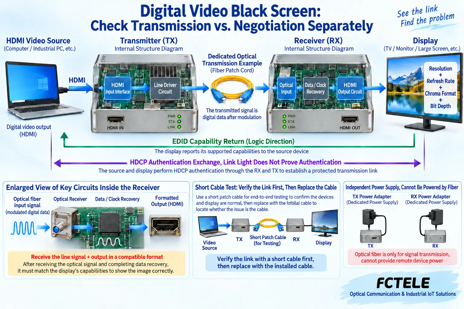
A digital video link must recover data and timing after receiving the signal, then output a supported format to the display. Insufficient link quality may cause loss of lock, errors, or intermittent black screen, which is not the same process as analog VGA edges gradually slowing. Fiber solutions should check fiber type, paired optical ports, connectors, and receive conditions; digital optical line loss cannot be directly explained as analog color fading.
Format records cannot just say “4K”; they must also include refresh rate, chroma, bit depth, and required audio. The source, transceiver devices, adapter stages, and display must all support the same target combination. After troubleshooting with a lower mode, return to the original mode to verify. Optical path measurement requires applicable tools; do not look directly at interfaces that may carry light; distance claims also cannot replace the loss and receive range of the entire line.
EDID, content protection, and IP connection each look at one layer
EDID is capability information provided by the display end, helping the source decide the output mode; HDCP is an authentication mechanism for applicable content, and a successful desktop display cannot replace full authentication compatibility. Some devices support capability learning or fixed settings; before use, save the original configuration and operate according to the manual. Copying arbitrary EDID, bypassing content protection, or forcing an unknown mode are not reliable repair solutions.
RJ45 is only the connector shape; a dedicated video twisted pair interface does not necessarily run Ethernet, and you cannot casually plug it into a switch or PoE port. IP-based solutions also need to check the matching encoder/decoder, address, VLAN, unicast or multicast, and actual load. The management web page being accessible only shows that part of the management path conditions are met; it does not prove that the corresponding video stream has reached the correct receiver.
How Feichang Technology models correspond to check items
The Feichang Technology FCC-H1 details clearly describe HDMI to network, and list VLAN requirements when multiple pairs of devices use a switch, so you can check network pairing and isolation accordingly. The FCM-H1-4k2 details describe optical transmission and EDID return, so you can check display negotiation and the optical path accordingly. The two types of intermediate paths are different, and the network version’s connection method cannot be directly applied to dedicated optical transmission equipment.
Optional interfaces, optical configurations, and version descriptions in different locations on the page should be confirmed by the supplier according to the delivered physical item; you cannot assemble a maximum combination that a sample does not have, nor copy unconditional zero-latency promises. Third-party analog equalizer chip information is only used to explain general VGA mechanisms; it does not prove that these Feichang Technology HDMI models use the same chip or provide analog video compensation knobs.
After recovery, complete acceptance according to the original business
Confirm the voltage, polarity, power capability, fixing, and heat dissipation at both ends, then let the actual fine text, color, dynamic picture, and sound run continuously. If USB or serial control is needed, test them separately, and finally run them together. Cover approved source restarts, display restarts, and link recovery, observe re-display and mode changes, and do not just save a screenshot of a chance bright screen.
The handover record should include the direct connection baseline, current mode, paired versions, line and power, each replacement or adjustment, and the corresponding result. If the abnormality still exists, tell the supplier the verified scope and uncovered conditions, and continue narrowing the scope by signal, line, configuration, and terminal. Only by distinguishing analog degradation, digital recovery, and display negotiation can you avoid attributing all faults to one long cable.
Data note: The principle diagrams have been checked against technical content and are used to explain general mechanisms; they are not product photos or measured records. Specific interfaces, modes, and capabilities are subject to the selected model, version, and on-site verification.
Verification materials: Analog Devices: Analog RGB line equalization mechanism
Analog Devices: RGB channel skew compensation mechanism
HDMI official cable classification
Feichang Technology FCC-H1 HDMI to network details
Feichang Technology FCM-H1-4k2 optical transmission details
Related technical topics: How does a network extender work? Distance and bandwidth boundaries for copper, coaxial, and fiberHow to wire a network extender? Up port, indicator lights, and NE300 usage checkHow to connect an HDMI extender: differences between point-to-point network cable, fiber, and IP networkHow to choose a network extender and calculate price? Line bandwidth, power, and complete set costWhat types of signal extenders are there: interfaces, transmission media, and compatibility boundaries
Translated from the Chinese technical article. Source first published: 2019-12-06. Source last revised: 2026-10-13T10:41:21+08:00. Read the Chinese source
