


An extender is most easily misunderstood as a connector that just makes a cable longer. In reality, when a cable is too long, the signal may become weaker or distorted, or the communication process required by the interface may not be able to complete. An active extender must receive and send again, or even convert the transmission method, to carry the service farther. Video, USB, and Ethernet have different rules, so the extenders they use are also different. First look at what it does in the middle of the signal, then discuss cable and distance, to avoid buying a device that can be plugged in but cannot work.
The interface name determines which type of device is needed
To send a computer image to a large screen far away, you first need to know whether the computer output is HDMI or another interface. If you also want to use a keyboard and mouse at the same time, that adds another USB service. Both appear to start from the computer, but they need different communication mechanisms. HDMI cares about image format and display capability. USB cares about how the host recognizes peripherals and exchanges requests. Ethernet transmits data according to its own frame and link rules. Some combination devices put them in the same product, but that does not mean any single-function extender can also complete the remaining tasks along the way.
Any extender cannot be treated as a universal multi-interface converter.
How DP, DVI, and KVM fit into the classification
DP, DVI, and HDMI are display interfaces that need to be checked separately. You cannot assume that the same extender can be directly interchanged just because they are all used for screens.
KVM describes the combined use requirement of keyboard, video, and mouse, and usually requires checking both the video and peripheral paths at the same time. The fact that a keyboard and mouse work does not mean a camera, storage, or all USB devices will work. IP KVM also involves network sessions, permissions, and supporting software, and its deployment method is different from dedicated point-to-point extension. When choosing fiber, first determine the direction of each service, the transmit-receive pairing, and the power supply, then do a short optical path baseline and formal line verification. “Fiber extension” is only a medium classification and cannot replace interface classification.
Why active devices can transmit in segments
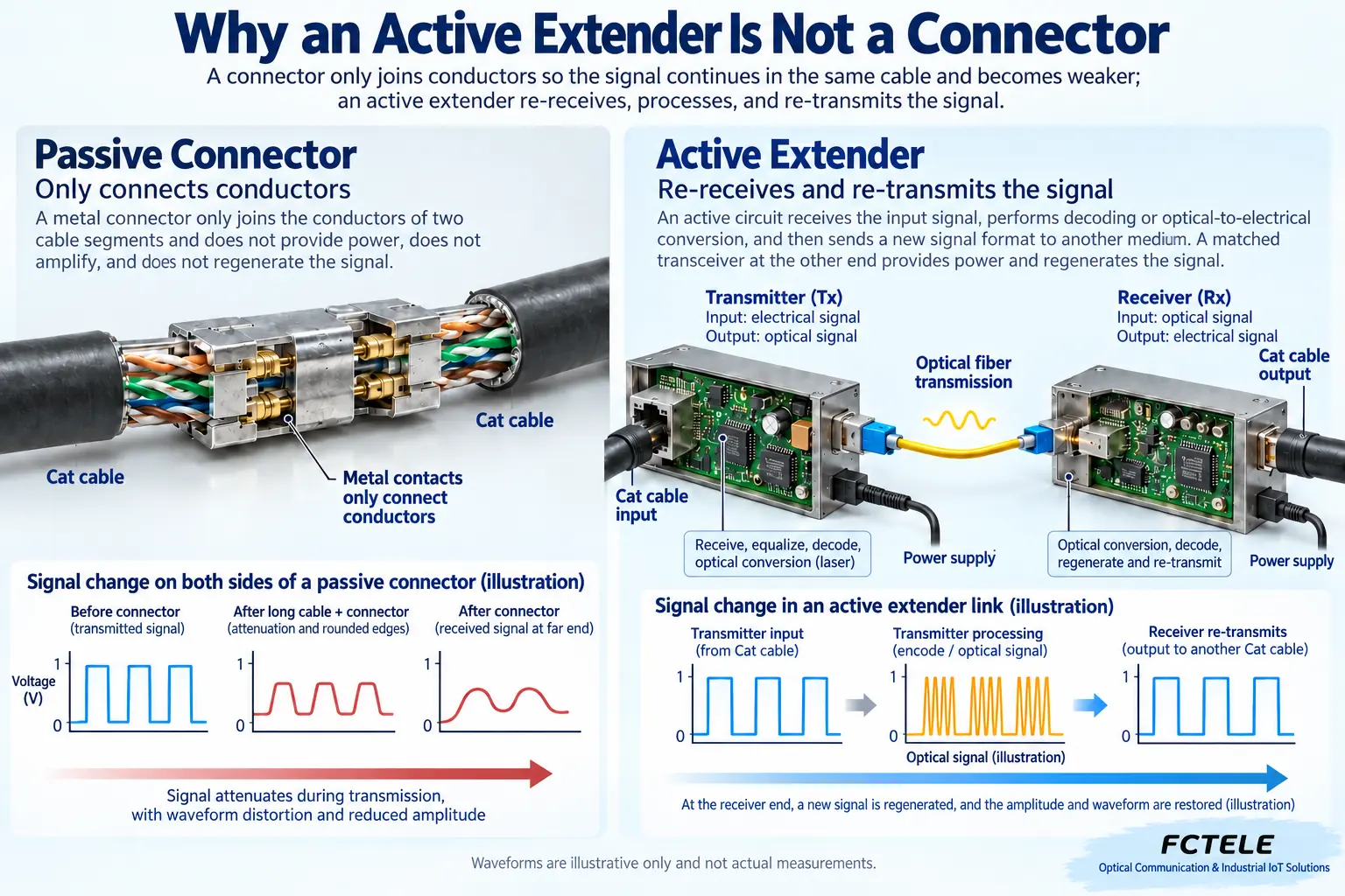
Figure 1 compares a passive connector with an active device. A connector only continues the conductor. The attenuation, reflection, and noise in the line will not automatically disappear just because there is one more connector. An active device uses electronic circuits to receive the input and then send it to the next segment according to the supported mechanism. It can reshape, encode, or convert to optical transmission. But the receiving step must succeed first. Severely damaged information cannot be recovered indefinitely. Power supply, input quality, a compatible receiving end, and output format are all indispensable. It is more like a transfer station with rules, not simply turning up the signal volume.
An ordinary connector only connects conductors and does not restore signal quality. An active extension device may receive and resend the signal, or convert the original interface data into a form suitable for long-distance transmission. The regeneration process depends on power supply, a compatible receiving end, and correct timing. Some solutions also introduce encoding compression or buffering. Extension does not equal zero delay, and it does not equal preserving every signal detail. You should ask about the output format and additional functions under real service conditions, and not compare only one number such as “maximum distance.”
A twisted pair interface cannot necessarily connect to a switch
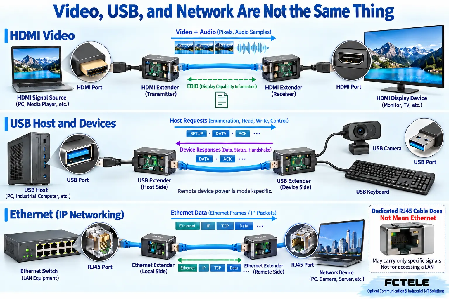
RJ45 is only a common connector shape. Inside, it can carry ordinary Ethernet, or it can carry a dedicated video or USB extension channel. Figure 2 uses different service routes to explain this: a dedicated channel must be directly connected to the matching two ends according to the instructions. A networked solution may encode the service into data that can be forwarded through a switch. First check the connection method clearly stated by the product. Do not automatically understand “uses network cable” as “can enter the network.” In particular, do not casually connect it to a powered PoE port to test compatibility. The same shape does not mean the power supply method is safely matched.
Some audio-video or USB extenders use RJ45 connectors and twisted pair cable, but the link does not carry ordinary Ethernet data and must be directly connected to matching transmitter and receiver ends. Other products use networked transmission and can pass through specified network equipment, but may require multicast, bandwidth, or management configuration. During installation, mark the purpose of dedicated links. Do not casually insert ports with the same shape into a PoE switch. Whether network switching, point-to-multipoint, and cascading are supported must all be confirmed by product documentation and actual testing.
Fiber and copper cable solve different cabling problems
Different media each have advantages and limits. Copper cable is convenient to install, but quality, length, connectors, and on-site interference can affect the received signal. Fiber avoids this section of conductor connection and is suitable for some longer-distance solutions, but it still requires a power budget and end-face maintenance. Whether both ends need power, how control services return, and whether modules can be replaced should be asked clearly before installation. So-called single-fiber, dual-fiber, or integrated optical cable also changes installation and spare parts methods. You cannot choose by ranking kilometers alone. Whether a certain segment can be replaced separately during later maintenance is also part of the cost.
Copper cable solutions need to check cable category, connectors, length, and interference environment. You cannot conclude that high-speed service is qualified just because ordinary network cable conducts. Fiber is suitable for some long-distance or electrical isolation needs, but it still has insertion loss, bending limits, and power range. The transmit and receive ends may also need independent power. Single-mode, multimode, fiber core count, and end-face type must match. When using an integrated active optical cable, also check plug direction and bending radius. After installation, end-to-end service still needs to be verified.
Write hidden requirements into the acceptance table
Enumeration in USB can be simply understood as the computer first asking “who are you and what can you do,” and the peripheral answers according to the rules before normal use begins. The fact that a keyboard works does not prove that a USB camera will also work, because device type, data method, and bandwidth requirements may be different. Some real-time audio and video transmission methods are more sensitive to timing. Whether they are supported must be checked in the product. HDMI also has to handle display capability negotiation, and a network link depends on actual frame forwarding. So the same physical cable having light, power, or an illuminated lamp only solves part of the entire service chain.
For video, check resolution, frame rate, color, audio, and EDID and HDCP. For USB, check version, device type, power supply, and isochronous transfer support. For Ethernet, check actual speed, throughput, packet loss, and whether the required services are carried. If keyboard and mouse, touch, infrared, or serial control are required, list the interfaces and directions item by item. Power-off restart, hot plugging, and signal source switching often expose compatibility problems. These should be reproduced before delivery. Do not use a static image lighting up as the entire acceptance test.
Example: control room computer connected to remote display and keyboard-mouse
Testing the system by breaking it apart is often faster than repeatedly changing cables. First verify directly that the computer, display, and peripherals themselves work normally. Then connect a short-link extender and check the image, audio, keyboard and mouse, and other functions item by item. Finally switch to the formal line. Add only one variable at a time and record at which step the fault appears. If the screen is black but USB works, first check the video chain for format and handshaking. If the image is normal but peripherals drop offline, first check the USB chain for power supply, device type, and reconnection. Do not use one successful function to prove that the whole set of equipment is compatible.
First split the video display and USB peripherals into two requirements, and confirm the display format, USB device list, and on-site cabling. Choose a matching product that explicitly supports these services. First test the image, keyboard and mouse, and re-enumeration on a short link, then connect the formal cable. If the display is normal but the keyboard drops offline, do not immediately replace the display. Check along USB power supply, device support, and the transmission link. Keep the direct-connection test results and extender settings to prevent misjudging compatibility when resolution is upgraded or peripherals are added in the future.
Common question: Does an extender always have no delay and always avoid compression?
No. Products may use different encoding, buffering, and transmission mechanisms, and may also perform conversion beyond pure transmission. What users really need is image quality, delay, and recovery behavior acceptable under the target service, not unconditional promotional words. You can ask the manufacturer to provide supported formats and test conditions, then verify with actual operation. Functions not clearly stated in the documentation should first be listed as to be confirmed. Do not try to discover them by repeatedly plugging into unknown ports or adding power yourself.
Translated from the Chinese technical article. Source first published: 2019-12-06. Source last revised: 2026-10-13T10:41:21+08:00. Read the Chinese source
