


First look at how data travels, not how many pins the connector has
Serial and parallel describe how data is transmitted. Serial splits a group of data into consecutive bits and sends them one after another along the corresponding channel; parallel expresses a group of bits at the same time on multiple data lines. Traditional computer serial ports and parallel printer ports are specific applications of these two methods, but they cannot be equated with all serial and parallel technologies, and one cannot directly conclude that one is always faster.
The most easily confused thing on site is the connector shape. DB9 is common on traditional serial ports, while DB25 was used both for serial ports and for parallel printer interfaces; the same shell shape cannot prove that the wire order, voltage, and software protocol are the same. Before buying a converter, you should find the device manual and confirm the port name, signal definitions, and purpose, rather than counting pins or trying to plug the connector in.
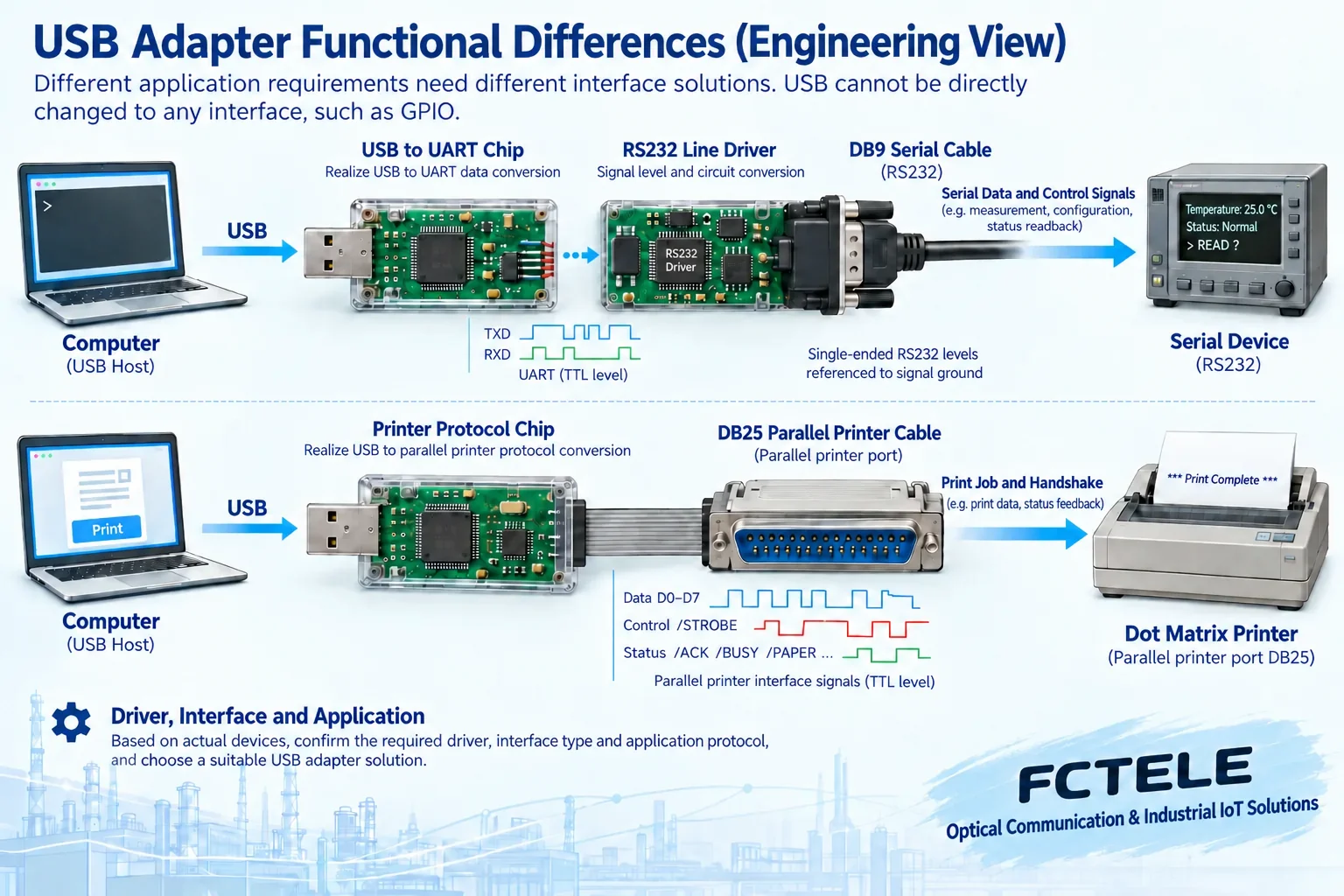
USB itself is also serial communication, but a USB device is not the same as a traditional COM serial port. A computer needs the corresponding driver and device function to use a USB-to-serial or USB printer adapter. Understanding USB as a cable that can convert any old interface would ignore the protocol handling, electrical circuits, and software support inside the adapter.
How UART sends one byte out bit by bit
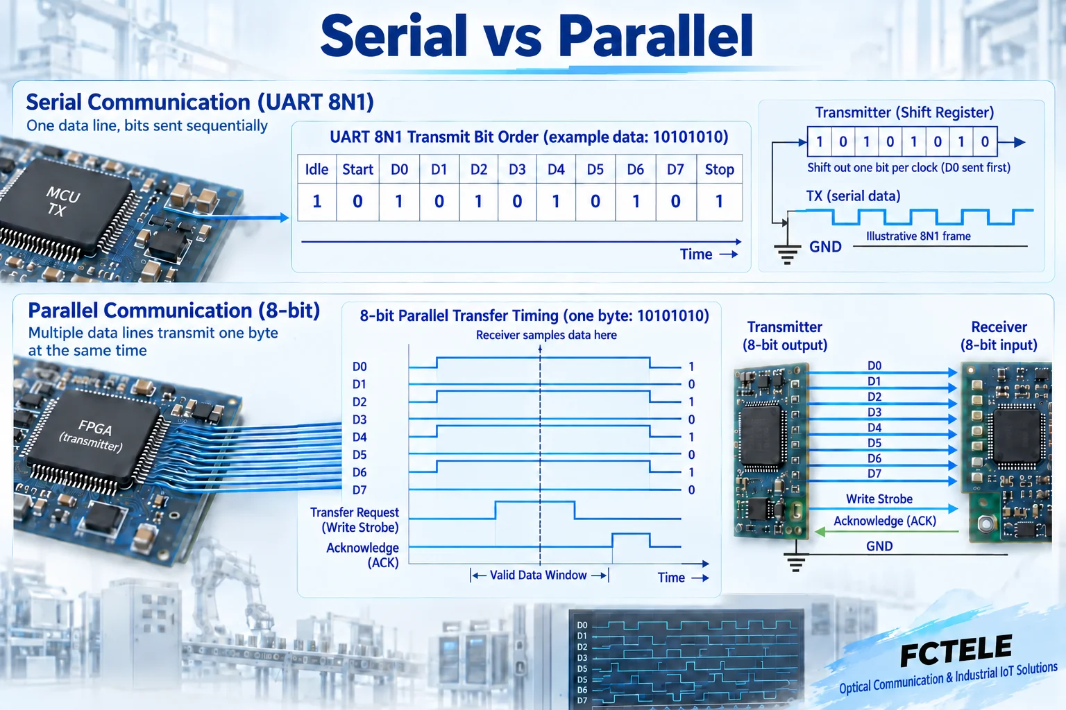
UART is a common asynchronous serial transceiver circuit. It is responsible for turning bytes handed over by software into bits arranged by time, and also reassembling received bits into bytes. Asynchronous means that the sending and receiving ends do not share an extra bit-by-bit clock line; the receiving end samples according to the start bit and the rate agreed by both sides. It is not without timing requirements; if the rate, data bits, parity, and stop bits do not match, reception errors can still occur.
Take the common 8N1 as an example: idle is at a high logic level, first a low-level start bit is sent, then 8 data bits are sent in sequence, usually with the least significant bit D0 sent first, and finally a high-level stop bit. N means no parity bit. In this logic example, one byte takes 10 bit times, and only 8 of them are data; the effective payload of continuous transmission cannot be directly equated with the line bit rate.
The high and low levels in the figure are an illustration of the UART logic layer, not the actual voltage on an RS232 plug. UART can be followed by RS232 or another electrical transceiver circuit, which then converts the logic values into the signals specified by the line. The UART format and the RS232 electrical interface must be checked separately; correct voltage conversion does not mean the application message has been understood or converted.
Why does a parallel interface still need handshake signals?
Take one basic transmission process of a traditional 8-bit parallel printer interface as an example: the sending end first places one byte on the eight lines D0 to D7, then uses a strobe signal to tell the receiving end that the data can be taken. The receiving end coordinates the next transmission with the sending end according to control signals such as busy status and acknowledgment. Different operating modes may use different directions and timing, and this basic example cannot be treated as the complete specification of all parallel buses.
Sending at the same time does not mean that the voltages on the eight lines all arrive at the same instant. Cables, drivers, and loads cause differences, and the receiver needs to sample within a time window when the data is already stable and has not yet changed. This involves setup time and hold time: the data must remain stable for enough time before and after sampling. Increasing the number of data lines also increases the work of wire order, grounding, crosstalk, and synchronization checking.
Serial and parallel cannot be compared only by speed
The common settings of traditional serial ports are relatively low, but that does not mean serial technology can naturally only transmit low-speed data. USB, Ethernet, and many high-speed interfaces use serial methods and rely on different encoding, electrical design, and clock recovery to achieve higher capacity. They are not obtained by simply raising the old RS232 rate at will; the device, cable, protocol, and software all need corresponding support.
Parallel can send multiple bits at once, but actual efficiency is also affected by handshake waiting, software scheduling, operating mode, and the processing capability of the receiving end. Serial has overhead such as start, stop, parity, or protocol headers. When comparing old devices, you should measure the time and error rate required for it to actually complete a task, and check the cable length and environmental requirements, rather than replacing specific specifications with “parallel is definitely fast, serial is definitely long-distance.”
Why USB adapters cannot be freely interchanged
A USB-to-serial adapter usually consists of USB interface handling, UART, and an electrical transceiver. The computer sends data through the serial port function provided by the driver, and the adapter outputs the agreed serial signal on the other side. Whether it supports RS232, RS422, or RS485, and whether it has control lines such as RTS/CTS, depends on the specific model; the appearance of a DB9 connector or a COM number in the software is not enough to prove that these capabilities are complete.
USB-to-parallel printer adapters mainly serve supported printing business. It may convert print data submitted by the computer to an old printer interface, but it does not necessarily provide the original hardware port registers to the application, nor does it necessarily support software precisely controlling each data line, strobe line, or reading peripheral status. Systems that once used a parallel port for acquisition, dongles, or control cannot infer that they can also be migrated directly just because a printer can print.
Conversion between serial and parallel ports is also not just about resoldering a cable. In addition to electrical connections, data buffering, serial-to-parallel conversion, handshake handling, and application protocol cooperation may also be needed. If the message meanings at both ends are different, protocol conversion is also needed. When purchasing, clarify whether the other end expects a byte stream, print commands, or some kind of control interface, to avoid using the name of an interface converter to cover all differences.
What kind of extension does the Feichang serial server solve?
Feichang product center number 2855 corresponds to the FCT-1500 industrial serial server. The product page lists 1 to 4 RS232/RS422/RS485 serial ports, 2 100 Mbps Ethernet electrical ports, and 1 100 Mbps optical port. Its role is to let supported serial devices connect to or extend through the network. The specific port count, electrical mode, and transport method must be checked according to the ordered version and configuration. It is not a traditional parallel printer port converter.
After the data of the serial device enters the server, it is transported to the host or remote end by the selected network mode, and then processed by the corresponding software or device. The page lists TCP, UDP, and related protocol modes; transparent byte transport, virtual serial port access, and application protocol conversion are different working methods. You cannot infer that it will automatically interpret all instrument commands or preserve the timing of all old parallel port control software just because the serial port can connect to the network.
The optical port can help serial business cross on-site distances through a matching Ethernet optical link, but the serial electrical section, network transport section, and application response are still three objects to check. When choosing equipment, you should confirm the transmit and receive direction, half-duplex or full-duplex conditions, connection wire order, network session and timeout requirements, and then confirm the optical module or optical port matching. Adding fiber does not automatically increase the bit rate set by the terminal serial port.
How to take fewer detours when migrating old devices
First record the original system: device interface description, actual cable, driver, port parameters, and one normal communication process. If it is a traditional parallel port, especially check whether the software directly accesses the hardware, whether it needs to read status in reverse, or whether strict handshaking is required. If it is a serial port, check the data format, control lines, timeout, and application protocol. Without this information, gathering evidence first is more effective than repeatedly buying conversion cables with different appearances.
Then use a short cable and a known-good peer for comparison to verify a single send and receive, continuous operation, and recovery behavior. A serial loopback can only prove part of the send and receive link, not that the real instrument command has been correctly executed; a parallel printer test can only prove the corresponding printing function. Final acceptance should use the actual business, record the results under disconnection and reconnection, device restart, and load changes, and keep the adapter model, driver version, and parameters, so that it can be judged whether the migration is complete.
Source note: principle diagram, checked by technical content, used to explain general mechanisms, not a product photo or measured record. Specific interfaces, modes, and capabilities are subject to the selected model, version, and on-site verification.
Verification sources: TI: UART protocol and error overview
IEEE 1284: Computer bidirectional parallel peripheral interface
Feichang FCT-1500 industrial serial server
Feichang serial server category
Related technical topic: What is a reverse bridge: the difference between E1 over IP, circuit emulation, and Ethernet bridging
Translated from the Chinese technical article. Source first published: 2024-06-28. Source last revised: 2026-10-13T10:22:10+08:00. Read the Chinese source
