


When choosing a serial server network mode, first ask who initiates the connection, then ask whether the application needs an ordered byte stream or independent datagrams, and only then adjust packing time and length. TCP Server, TCP Client, UDP, and protocol conversion are not at the same decision level; just because menu items are placed together does not mean they differ only in speed.
1. Mode selection starts from the software role
A serial server moves bytes between the network and the serial port, and the host application is responsible for interpreting the application data. If a computer program actively connects to a field device, the field side is usually configured as TCP Server; if a central program waits for field devices to connect in, the field side is usually configured as TCP Client. If both sides wait, even if the network is reachable, a connection will not appear by itself.
Connection roles do not restrict data direction. After a TCP connection is established, both ends can usually send and receive bytes, so the server side is not only able to receive, and the client side is not only able to send. The example port must be kept consistent at both ends; the management web page port and the instrument application port serve different purposes, and you cannot judge that the application is normal just because the web page opens.
2. What is the difference between TCP server and client?
The server listens on a specified address and port, and the client actively requests a connection. Only after the client initiates and the server accepts can the application transmit data over that connection. When configuring the client, you also need to fill in the destination address and destination port; when configuring the server, you confirm the listening range, application port, and allowed connection sources.
When a device initiates a connection, whether it maintains a long connection, and how long it retries after disconnection are firmware and configuration behaviors. Some devices connect on power-up, and some support serial data triggering; you cannot apply one menu behavior to all models. The mode name describes the basic role and cannot prove that registration packets, encryption, or disconnection buffering definitely exist.
3. Why UDP cannot be understood merely as faster TCP
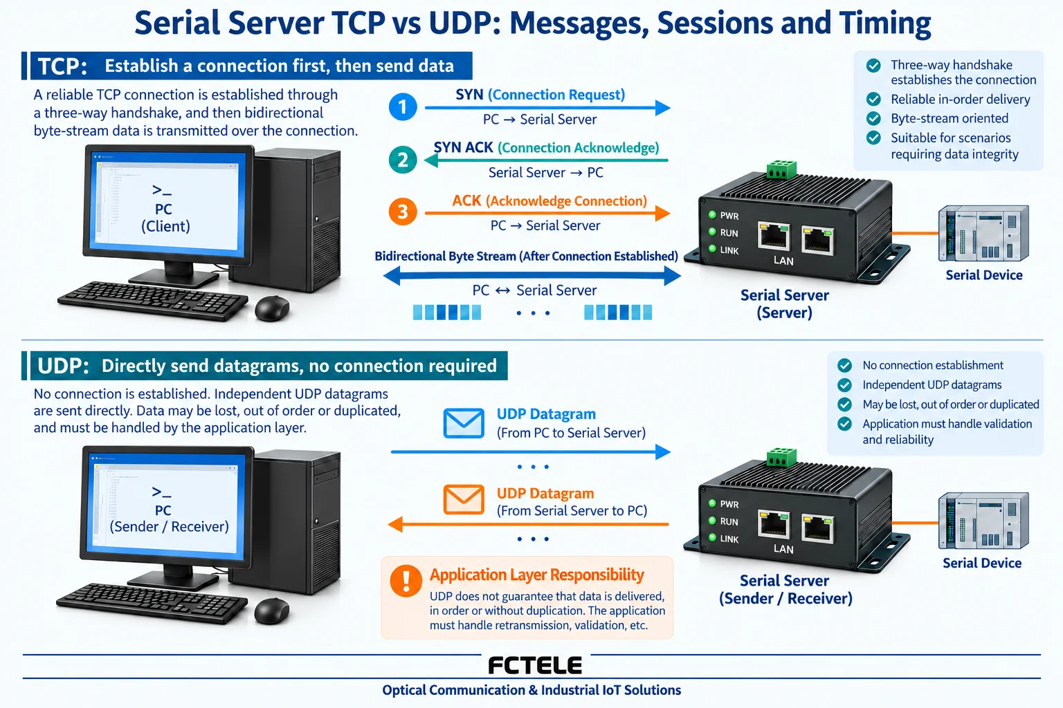
UDP sends datagrams, does not establish a TCP-style connection, and does not itself guarantee ordered arrival, reliable delivery, or duplicate protection. It preserves datagram boundaries, but this boundary does not necessarily equal the serial protocol message boundary, because the serial server may form datagrams according to packing conditions.
If the application uses UDP, it must consider packet loss, out-of-order delivery, duplication, and insufficient receive buffering, and define sequence numbers, acknowledgments, or other recovery rules according to the application. The risk of read-only periodic sampling and control commands is different: a start/stop command cannot omit execution status verification just because UDP has no handshake.
UDP Server and UDP Client in menus are often used to express listening, destination address, or response strategy; they are not a complete correspondence to TCP connection roles. Some devices send back to a fixed destination, and some send back according to the source; whether multiple sources can be received and how responses are allocated should all be checked in the manual. Broadcast addresses and ports do not have a unified industry-wide default value, and the numbers listed in old articles should not be used directly for other products.
4. Why serial packing adds waiting
Serial bytes arrive one after another, and the device needs to decide when to hand them to the network for sending. Common conditions include accumulated byte count, interval time, or delimiter characters. Reaching the length condition can trigger sending, and waiting until the specified interval may also trigger sending; how conditions are combined and what a value of zero means differ among manufacturers.
Suppose a short reply has only a few bytes, but the packing length is set very large, and the device may continue waiting for the interval condition. If the host computer timeout is too short, it will judge the reply still in the buffer as a failure. Conversely, packing too frequently produces many small data blocks and increases processing overhead. You should test based on reply length, serial speed, and application cycle.
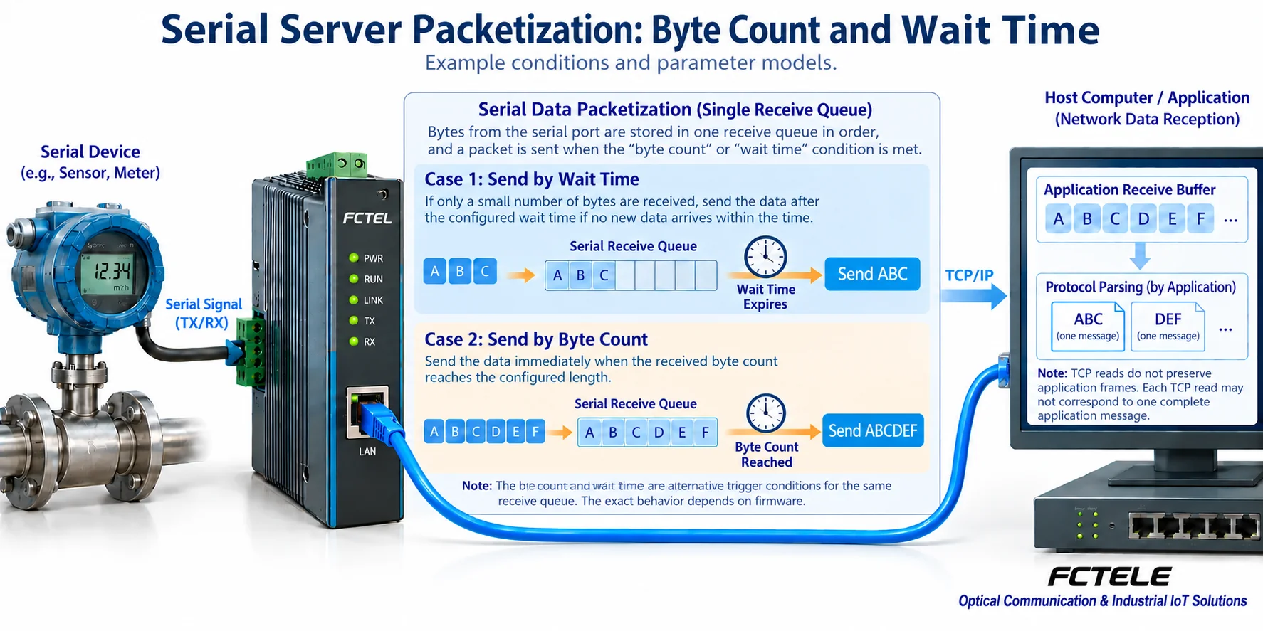
When TCP delivers normally, it provides an ordered byte stream, and one program read may obtain half a frame or multiple frames. Adjusting packing parameters cannot replace application framing. The application still needs to judge the complete message by length, delimiter, checksum, or protocol state, and then interpret the content; treating each read directly as one reply easily causes occasional errors.
5. Keepalive, idle timeout, and application timeout must be separated
Keepalive is used to detect whether a connection may still be valid, idle timeout is used to close a session with no activity for a long time according to configuration, and application timeout is the deadline for the application to wait for a device response. These three solve different problems, and you cannot use one keepalive time to infer how long an instrument should take to reply.
Keepalive packets and probe counts are determined by system and device implementation, and you should not copy ‘close after three no-responses’ as a unified standard. Connection recovery also does not mean the previous control command was not executed. Before timeout retry, consider whether the command can be safely repeated, and if necessary query the status first or use a transaction mechanism supported by the protocol.
6. Multiple connections and Modbus conversion are not the same capability
Allowing multiple TCP sessions only indicates network access capability. If multiple masters write to the same RS485 bus at the same time, request conflicts may occur, and responses may be attributed incorrectly. You need to check whether the device provides arbitration, queuing, read-only access, or an explicit gateway mode, and coordinate it through the overall solution.
Modbus RTU to TCP requires correctly handling the two types of message structures and transaction correspondence; it is not completed by simply sending RTU bytes onto TCP. The appearance of a ‘Modbus’ option in TCP mode also cannot prove that all devices support it. The maximum session count, preemption rules, and menu range in old articles that lack specific model basis are not retained here as general specifications.
7. Complete field configuration and acceptance in order
First record the host computer role, terminal interface, and serial format, then plan the network address, port, and access range. In an isolated test environment, use one known terminal to complete bidirectional application, and observe connection status, serial counts, and raw replies. Then adjust packing parameters, changing only one item at a time, and save a configuration that can be rolled back.
After connecting back to the field, test continuous polling, simultaneous load, and disconnection recovery, and check timeouts, reply content, and duplicate commands. TCP does not equal encryption; remote access must use a planned secure channel and access control, and do not directly expose the management web page or control port to the public internet. UDP likewise cannot omit source restrictions and authorization.
8. How to verify specific products
The Feichang Technology FCT-1500 series details list TCP Server/Client, UDP, virtual serial port, and Modbus-related modes, which can be selected and configured according to the host software and terminal protocol. For selection, first confirm the actual ordered interface, firmware-supported working modes, and conversion functions, then check connection count, packing, and reconnection parameters, and do not treat series promotion as a complete manual for every configuration.
If you are only judging general working modes, refer to 1197; for a coherent configuration example of a TCP server, refer to 2271. This article independently explains UDP and packing mechanisms to help readers understand why ‘switch to UDP’ and ‘set the time to zero’ are not universal solutions.
References: TCP specification ; UDP specification ; Feichang Technology FCT-1500 series details . The illustrations are general mechanism diagrams and do not represent actual measurements or specific model menus.
How to check old client and UDP configuration articles item by item
When the device acts as a TCP Client, first start listening in the central program, fill in the central reachable address and application listening port, then confirm the character format, channel, and bidirectional sending and receiving; the management web page address cannot replace the application target. Save the configuration and test the behavior after power cycling and disconnection. If short connections or multiple destinations are supported, confirm according to the corresponding model, and do not infer the upper limit from the Client name.
For UDP testing, record the local binding address and port, and the destination address and port separately. Sending to a fixed destination and responding according to source are different strategies, and which behavior the UDP Server or Client menu specifically uses depends on the manual. Do not fill contradictory ports in the same parameter field at both ends, and do not use TCP handshake to determine that UDP is online. First use a small amount of identifiable test data to check the bidirectional path, then verify how the application handles loss, duplication, and out-of-order delivery.
This article carries forward the valid content of the corresponding old article; the principle diagrams are general principle illustrations; general mechanisms and specific model capabilities are verified separately.
Translated from the Chinese technical article. Source first published: 2022-12-09. Source last revised: 2026-10-13T11:01:30+08:00. Read the Chinese source
