


Before maintenance, first identify which route the device belongs to
Daily maintenance of a protocol converter cannot use one universal DIP switch table. Telecom equipment may connect to E1, V.35, or Ethernet bearer, while industrial gateways may parse serial messages and map registers. Both types may have network ports, serial ports, or management pages, but their application objects are different, so the observation indicators and test methods are also different. First record the model, version, and complete connection relationship.
For example, Ethernet borrowing an E1 leased line requires confirming the bridges on both sides, the E1 line, and the application capacity; an industrial host computer reading an RS485 instrument requires confirming the gateway, serial station, and point table. Being able to ping the management address only proves that part of the network is reachable. It does not mean the E1 circuit is correct, nor does it mean the temperature value is correctly interpreted. Maintenance should start from a clear application direction.
Establish a normal baseline so there is something to compare against when a fault occurs
Save the port status, configurations at both ends, error and alarm counts, actual load, and test time at commissioning. For industrial systems, also save the station address, variable address, data type, word order, multiplier, normal refresh cycle, and quality status. For telecom systems, save conditions such as framing mode, time slots, clock source, cable, and interface impedance. Saving only device screenshots is usually not enough to restore service.
After a fault occurs, preserve the scene first, then decide whether to restart. Whether a count is cumulative or current, and whether an alarm is received locally or reported remotely, must be explained clearly. Change one parameter at a time and write down the results before and after. Restoring factory settings, upgrading firmware, or modifying channel mapping should have a maintenance window, a rollback configuration, and a specific operational basis, to avoid adding new problems on top of the original one.
For the telecom route, check the line and timing first
LOS on the E1 receive side indicates that the corresponding line has lost signal. First check upstream for its transmit output, wire pair, connector, and interface conditions. AIS is an alarm indication sent along the transmission direction and is different from a complete absence of signal; you need to combine records from both sides to locate where the alarm is generated. Alarm lamp names, thresholds, and display colors should be checked against the model and cannot be copied directly from another device.
If there is signal but frame alignment is unstable, also check whether framing and unframing, CRC mode, and frame parameters are consistent. When the service is down but line alarms are cleared, further check the time slots and mapping used. Intermittent slips may be related to a long-term frequency mismatch between read and write clocks, and are not a synonym for an ordinary Ethernet IP address conflict. Accurate management time also does not prove that the E1 output timing is qualified.
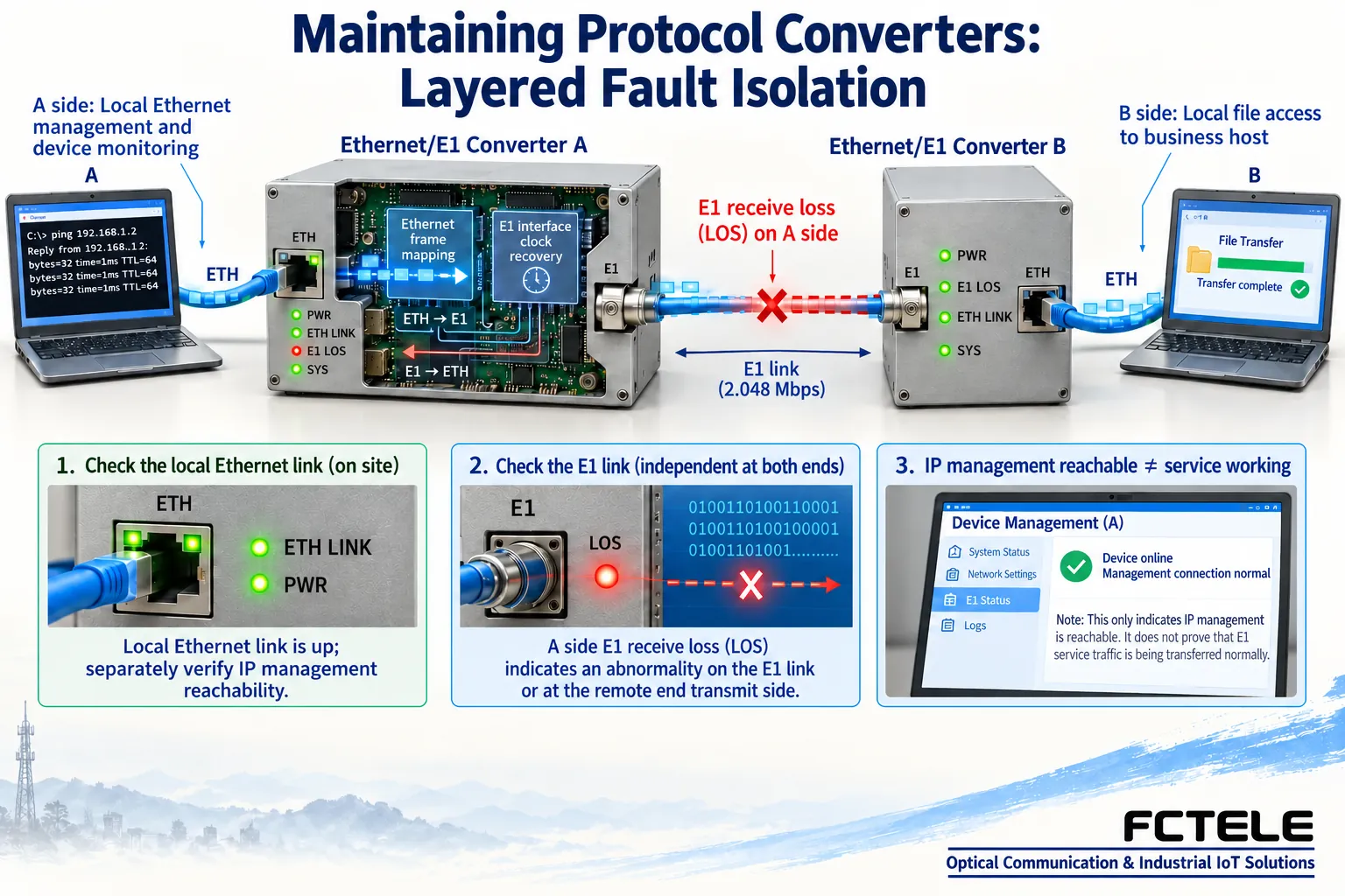
Why can cross-station communication still fail when the network port is normal?
The establishment of the electrical port link on an Ethernet-to-E1 bridge only shows that part of the conditions for the local Ethernet interface are met. The available capacity of the intermediate E1 line, encapsulation matching, and multi-channel configuration may still affect the service. A 100 Mbit/s electrical port cannot turn a 2.048 Mbit/s E1 line into a 100 Mbit/s leased line. Long-term excess traffic will cause queuing or discarding, and increasing buffer memory cannot create capacity.
If the service is E1 over IP, then you should check packet loss, out-of-order, and arrival interval changes on the actual bearer path, and verify the receive buffer and clock mode. This is a different direction from Ethernet over E1. Feichang Technology FCC-E1fF1 can serve as a product example for Ethernet and E1 interface conversion. Specific status and test functions should be checked against the delivered version, and it cannot be treated as maintenance instructions for all industrial gateways.
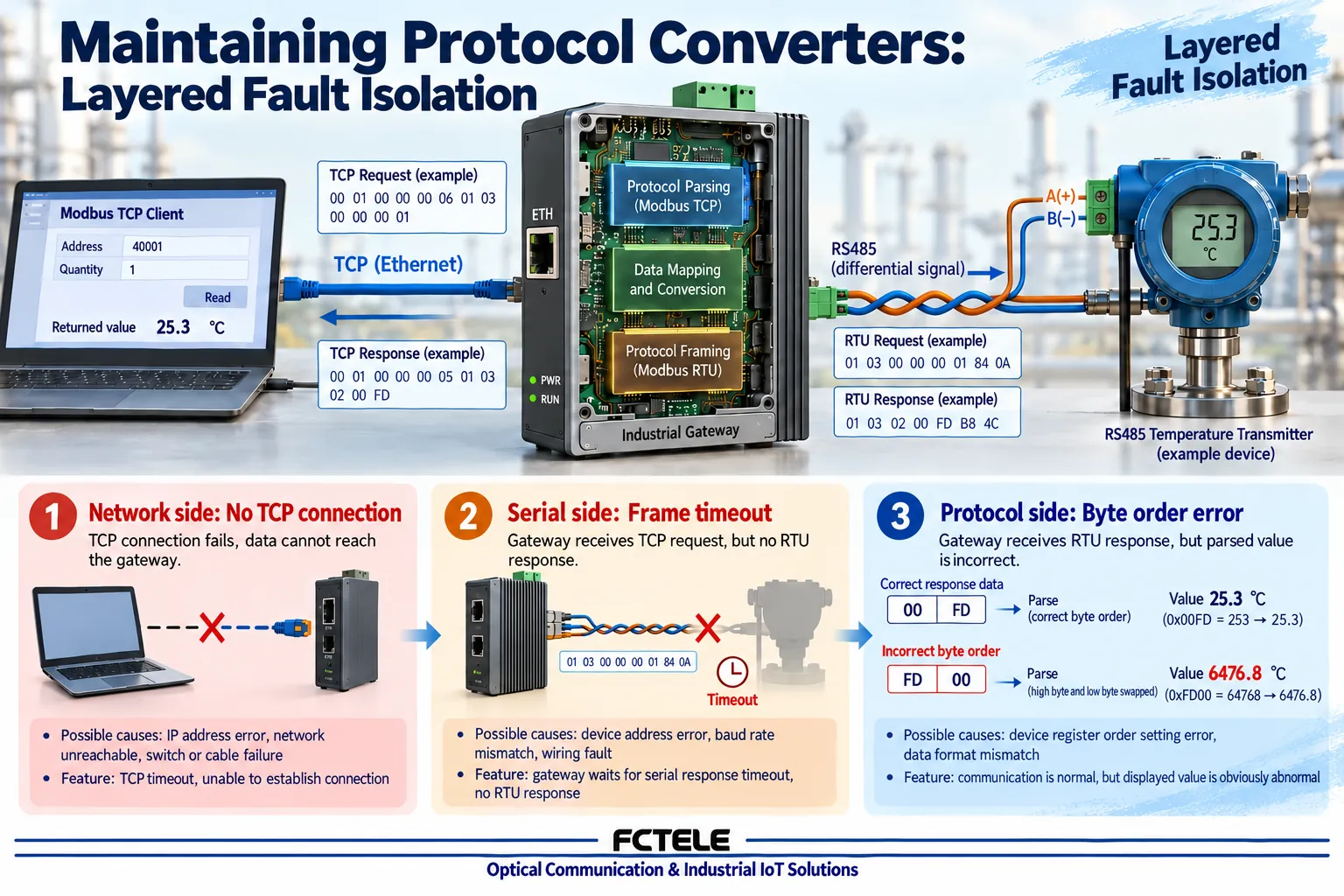
For the industrial route, check connection, messages, and values separately
When the host computer cannot establish a connection, first check the network address, port, access control, and connection role. When the connection exists but the serial instrument does not respond, check the wiring, rate, parity, station address, and target protocol. When an abnormal response is received, check the function code and access range. When a normal response is received but the value is abnormal, then check the data type, address offset, word order, and multiplier; do not immediately conclude that the sensor is damaged.
Save the source-side request, source-side response, and host value separately, so maintenance personnel can determine whether the gateway generated the correct message. When a transparent serial server only carries the original bytes, the host software still handles message interpretation; only a protocol gateway re-encapsulates according to supported rules. The log meanings and configurations of the two types of devices are different. Traffic on the network side does not mean that industrial protocol conversion has been completed.
Monitoring should reveal old values and invalid states
Monitoring items should serve fault location: connection interruption, serial timeout, abnormal response, checksum error, update cycle, and data quality are more direct than monitoring CPU usage alone. A temperature that stays unchanged for a long time may be truly stable, or it may be a cached value that is stuck; sampling time or update evidence is needed. When disconnected, there should be a clear expired or invalid state, so the host system does not continue to treat the old value as real-time data.
A timeout at one faulty station may also lengthen the polling cycle of other stations. Record retry and waiting trends, and appropriately limit the occupation by the faulty station. Network management software can obtain relevant indicators only when the product provides the corresponding interface; do not assume that every converter supports SNMP, remote control, automatic recovery, or encryption. Logs, alarms, and configuration permissions should also be checked separately.
Check power, environment, and upgrades according to the version
Inspect device fixation, ventilation, grounding, cable stress, and rated power supply, and check for water ingress, loose connectors, and abnormal heating. Do not treat the voltage range in an article as a universal specification for all models, and do not try connecting live when the terminal definitions are unknown. If the device smokes, smells, or is obviously damaged, stop using it according to the manual and have it handled by qualified personnel.
Before upgrading, confirm that the firmware and hardware versions match, whether the configuration format is compatible, and whether the communication mode will change, and save a recoverable old configuration and support materials. After upgrading, not only check the management page, but also re-verify the service, data quality, and disconnection recovery. Remote maintenance entrances should limit access sources and permissions, and industrial protocols or management services should not be directly exposed to the public network.
Use real services to complete recovery acceptance
After the telecom system exits loopback or test codes, verify the bidirectional channel, timing, actual load, and alarm trends. The industrial system should verify known variables, request correspondence, read/write permissions, refresh cycle, and abnormal flags. Passing a short line or local loopback only proves the path it covers and cannot replace remote devices and application verification not included in the test.
Finally, record the fault symptom, locating evidence, actions taken, recovery time, and retest conditions. Keep configurations, topology, and count trends, so next time similar faults and new problems can be distinguished. The goal of maintenance is to restore an explainable service link: telecom types check line, mapping, and timing; industrial types check messages, point table, and timeliness. The shared network port appearance of the two does not erase these differences.
Data note: The principle diagrams have been checked against technical content and are used to explain general mechanisms. They are not product photos or measured records. Specific interfaces, modes, and capabilities are subject to the selected model, version, and on-site verification.
Verification materials: ITU-T G.704 framing structure
Feichang Technology FCC-E1V1 product information
Feichang Technology FCC-E1fF1 product information
Modbus application protocol
Feichang Technology FCT-1400 serial server information
Translated from the Chinese technical article. Source first published: 2024-05-06. Source last revised: 2026-10-13T13:23:07+08:00. Read the Chinese source
