


The E1 line is already connected, but synchronization is unstable or intermittent errors appear. You cannot judge interface matching only by the shape of the connector. A 75Ω unbalanced coaxial interface and a 120Ω balanced pair have different electrical conditions. Incorrect termination or wiring may cause pulses to reflect. When matching is needed, you can choose a corresponding E1 impedance converter, but it only performs interface adaptation. It is not a universal repair device that regenerates data. This article explains reflection and acceptance around the E1 interface, and does not directly apply matching methods from RF antennas or high-speed chips.
1. Why errors may still occur even when continuity is normal
A multimeter continuity check mainly answers whether conductors are connected. A digital line also depends on how the signal propagates when it changes. A cable has distributed capacitance and inductance. A pulse traveling along the line does not make the entire line instantly reach the same voltage. Characteristic impedance describes the voltage-current relationship during this propagation. It is not equal to the DC resistance of the conductor. Loose connectors, wrong cable specifications, and unsuitable termination may change the electrical conditions during propagation.
When a traveling signal meets a mismatched boundary, part of it may continue forward, and another part may return toward the source. The returning part is called reflection. It adds to signals arriving later and may form ringing, overshoot, or other changes in pulse shape. Whether the change is enough to cause service errors also depends on input amplitude, receiver margin, line length, and the receiving circuit. You cannot see one connector and immediately declare that errors must exist.
A normal E1 nominal rate is 2.048 Mbit/s. One bit is about 488 nanoseconds. The line code is commonly HDB3, which uses positive, negative, and zero-level pulses with defined relationships to represent information. What is discussed here is the interface waveform. You cannot treat an internal logic square wave and an external E1 pulse as exactly the same electrical signal. Instrument observation must use suitable impedance and connection methods, so that the measurement connection itself does not change the line.
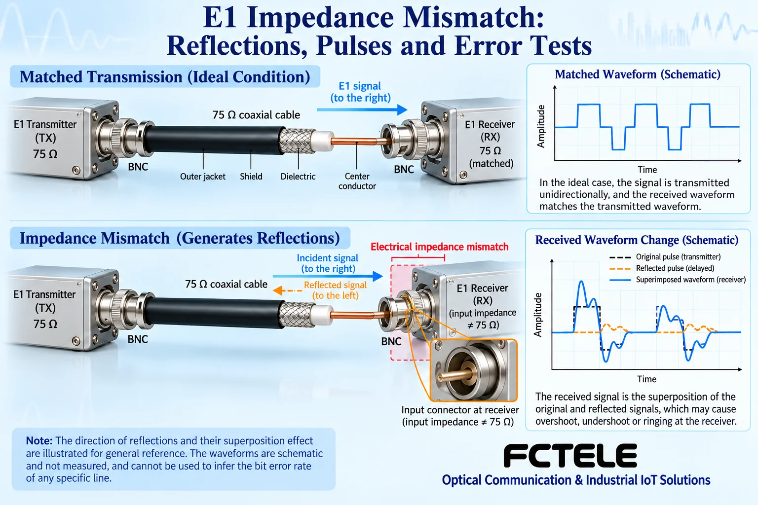
2. Balanced and unbalanced are different interface conditions
A 75Ω unbalanced E1 usually travels over coaxial cable. The center conductor and the corresponding outer return path form one direction. A 120Ω balanced E1 usually uses two conductors as a pair. The receiver mainly compares the voltage difference between the two conductors. To complete bidirectional service, transmit and receive paths must be arranged separately. Directly connecting different interfaces with an unknown adapter cable may introduce impedance, balance method, direction, or pin errors at the same time. It cannot be reduced to a single resistance value.
If both ends originally use the same correct interface, in principle first check the cable, connector, termination, and configuration. Do not blindly add adapters to “improve quality.” If one end is clearly 75Ω and the other end is clearly 120Ω, confirm the converter and matching cables according to the complete E1 interface requirements. Connector shape is only a clue: BNC or L9 connectors and RJ45 jacks each have mechanical definitions. The specific port purpose and pins still need to be confirmed from the equipment documentation.
3. What impedance conversion can solve and cannot solve
A suitable converter can establish a matching relationship between two electrical interfaces. A common passive method couples the changing signal through magnetic components and, according to the circuit design, completes adaptation of the balance method and voltage-current conditions. No external power does not mean there is no insertion loss, and it does not mean transmission distance can be directly increased. The entire link still must meet input/output, cable, and receiving conditions.
Feichang FCTEL FCCZ-E1-BNC, FCCZ-E16-BNC, FCCZ-E16-L9, and the official website 24-channel FCCZ-E34-BNC products provide E1 75Ω/120Ω conversion for the corresponding number of channels. Public information states that no external power is required. A single-channel unit is suitable for a small number of channel-by-channel handovers. Multi-channel equipment facilitates centralized cabling. BNC and L9 versions must also be selected according to the existing patch panel connectors. When confirming ordering information, record the number of channels, interface method, and transmit-receive correspondence at the same time. You cannot describe a 16-channel converter as increasing a single E1 channel to 16 times the rate.
A converter cannot replace clock recovery at the receiving end. It cannot automatically unify different service configurations at both ends. It also cannot turn Ethernet, video, or RF signals that are not originally E1 into interoperable E1 services. When there is a clock source conflict, inconsistent frame format, or the far end is not provisioned, check the corresponding equipment configuration. Only use it correctly at the electrical interface boundary. Then troubleshooting will not become more complicated with every change.
4. Why the receiver cares about both shape and timing
The receiving end must judge the encoded information from the input waveform and also process data according to suitable timing. If pulse amplitude and shape are unsuitable, decisions may be wrong. If the timing relationship is unsuitable, timing problems may also occur. Both problems can exist at the same time, but “impedance has been converted” does not prove that the clock is already correct. A specific Feichang passive converter does not therefore have retiming or network protocol processing functions.
Panel synchronization and alarm status can only provide partial evidence. When a line is just connected, a lamp may be on, and errors may appear only after it runs for a period. This may involve conditions such as temperature, connectors, clock, or service load. Record the time of occurrence and the status at both ends. Compare a short cable and the formal line under the same configuration. Verify physical interface problems, system clock problems, and service-layer problems separately.
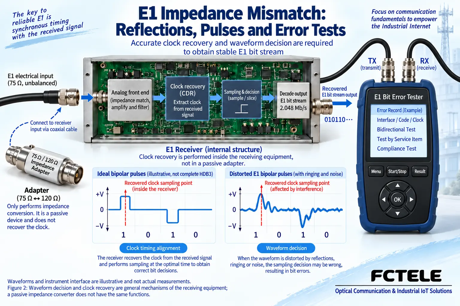
5. Use repeatable comparisons to find the problem boundary
First save the site configuration and wiring records. In an approved maintenance window, use a known-good short cable to establish a baseline. Confirm that the tester interface impedance, service port, encoding, and clock options meet the actual requirements. Then test both directions according to plan. After the short cable is normal, add the converter and matching cables that need to be used, and then connect the formal cabling. Change only one main condition at each step and record the results before and after the change. Only then is it easy to judge which section introduces the problem.
For multi-channel equipment, test channel by channel: clearly identify the local channel and the far-end channel, check both directions of that channel, and then observe the currently used channels running together. Testing should not look only at the first channel, and input alarms from reserved empty ports should not be treated as abnormalities on all currently used lines. If loopback is used, clarify the loopback location, test scope, and service impact. Exit loopback according to the manual and restore the original configuration, so that maintenance status is not left for formal service.
If normal reception cannot be established even with a short cable, first check interface selection, reversed transmit-receive, pins, and port status. If the short cable is normal but the site line is abnormal, compare cable specifications, connectors, cabling, and termination. If physical reception is stable but the application service does not work, then check frame, timeslot, clock, and service system configuration. Do not repeatedly plug and unplug with unknown wiring, and do not connect a suspected E1 RJ45 port to a PoE switch for trial and error.
6. How to form a handover-ready acceptance record
The record should include equipment and converter models at both ends, interface method, channel mapping, cable and cabling locations, tester configuration, clock selection, test duration, and observed errors and alarms. The test duration and judgment threshold should be specified by the project or maintenance requirements. You cannot promise long-term zero errors just because one short test showed no errors. For abnormalities, save the occurrence conditions, time, and recovery method for later reproduction.
The goal of site acceptance is to prove that under the specified conditions, the electrical interface and service operation of the line meet the requirements. Impedance matching is one part of this, not a separate endpoint. Mechanical adaptation, signal decision, clock, and service should all form a checkable relationship. To understand the specific converter channel counts and wiring, continue reading the corresponding E1 principles and selection articles. Avoid mixing problems at different layers into “the signal is not strong enough.”
Sources: ITU-T G.703 digital interface specifications ; Feichang single-channel E1 impedance converter ; Feichang 1–24 channel E1 products . General receiving mechanisms do not represent a specific product structure. The schematic is not a product photo, measured waveform, or certification material.
Related topics: How an E1 impedance converter works and how to select one: 75Ω/120Ω, transmit-receive wiring, and channel count ; How to read parameters of an 8E1 PDH optical multiplexer: eight services, impedance, and matching interfaces .
Common site questions
If E1 synchronization is unstable, will adding any impedance converter always improve it?
No. If both ends already use the same correct interface, first check cables, termination, transmit-receive, and configuration. Adding a device may introduce extra loss. When one end is clearly 75Ω unbalanced and the other is 120Ω balanced, then choose the corresponding adapter. Frame and clock conflicts are not automatically repaired by impedance conversion. Locate the cause layer by layer.
The E1 connector passes a continuity check. Why can intermittent errors still occur?
A continuity check cannot reflect pulse propagation and termination reflection. Cable material, connectors, and mismatched boundaries may change the waveform. Clock and temperature may also affect long-term performance. Use a suitable interface test method, compare a short cable and the formal line under the same configuration, and record alarms and the time errors occur. Do not treat one lit lamp or one resistance reading as signal quality acceptance.
A short cable test is normal, but the formal line is abnormal. How should troubleshooting continue?
Keep the verified equipment and configuration. Add the converter, cabling, and line section by section. Change one condition at a time and record the results in both directions. First check specifications, transmit-receive correspondence, and termination. If physical reception is stable but there is still no service, then check frame, timeslot, and clock. Loopback must note the scope and service impact, and must be removed afterward, so that test status is not left on the formal link.
Continue reading: How an E1 impedance converter works and how to select one: 75Ω/120Ω, transmit-receive wiring, and channel count ; How to judge interface compatibility of a PDH optical multiplexer: E1, Ethernet, and optical-side formats ;
Translated from the Chinese technical article. Source first published: 2024-07-08. Source last revised: 2026-10-15T22:31:43.863560+08:00. Read the Chinese source
