


An E1 impedance converter solves the problem of mismatched electrical interfaces at the two ends: when one end uses 75Ω unbalanced coaxial cable and the other end uses 120Ω balanced twisted pair, it completes signal coupling and impedance matching according to the correct specifications. It does not turn E1 into Ethernet, nor does it upgrade 2.048 Mbit/s to a higher service rate. Feichang Technology’s single-channel and multi-channel products suit different numbers of E1 handovers, and selection should start from the number of lines, interface form, and wiring definition.
1. What 75Ω and 120Ω actually describe
The ohm values here mainly describe the electrical conditions that the line and port present as the signal changes. They cannot be understood as the DC resistance of a piece of copper wire measured with a multimeter. As the signal travels along the line, when it encounters a connection different from the design, part of the energy may return and form a reflection. The reflection overlaps with the original pulse and changes the waveform seen at the receiver; connectors, cables, terminations, and device status together determine the final effect.
75Ω E1 usually uses unbalanced coaxial cable: the center conductor carries the signal, and the outer conductor provides the corresponding return path and shielding structure. 120Ω E1 usually uses a balanced pair: the receiver mainly compares the voltage difference between the two conductors. A complete bidirectional connection also needs separate arrangements for transmit and receive; one coaxial cable or one twisted pair cannot be treated as two independent directions.
The nominal line rate of E1 is 2.048 Mbit/s, and the common line code is HDB3. The encoded pulses have specified amplitude, shape, and timing requirements. Impedance conversion belongs to physical interface layer adaptation; whether the frame format, timeslot usage, service signaling, and system clock are compatible still must be checked by the corresponding equipment and service configuration. Matching the interface does not mean every layer of service is connected.
2. How a converter changes electrical conditions
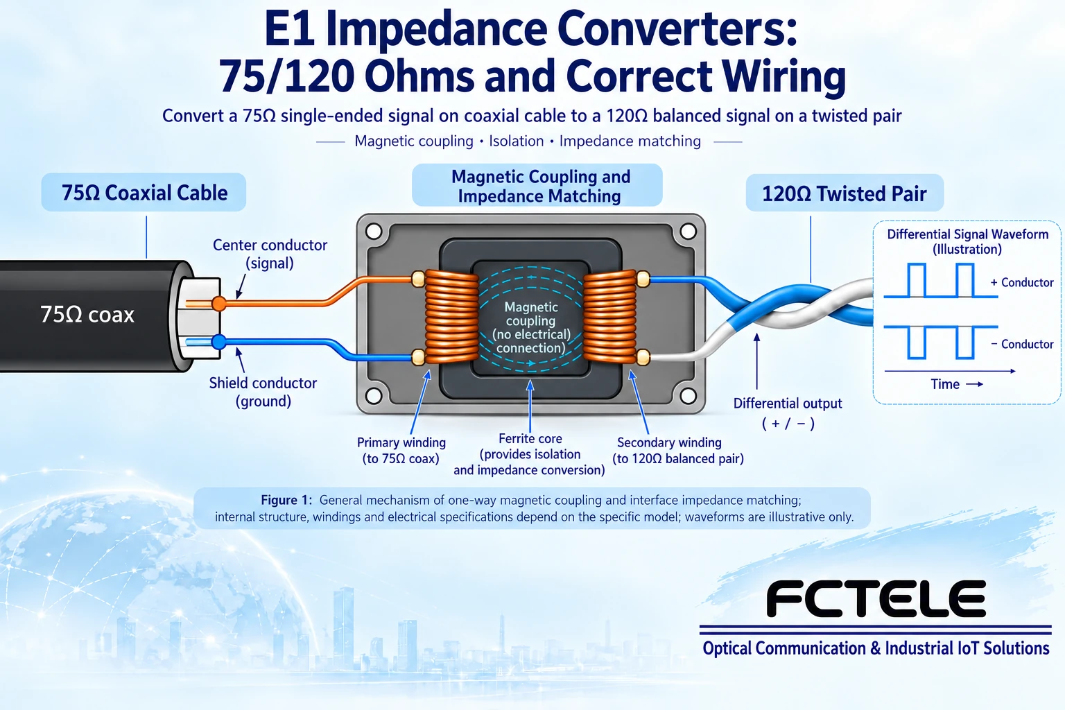
A common passive implementation uses a magnetic transformer for signal coupling: changing current in the input winding produces changing magnetic flux, and the output winding obtains the signal through magnetic coupling. The windings and circuit design together form the voltage and current relationship suitable for the interfaces on both sides, and adapt unbalanced and balanced connections. In an ideal transformer, the impedance seen is related to the square of the turns ratio; real equipment must also consider frequency response, parasitic parameters, and losses, so one cannot simply wind a replacement according to a mathematical ratio instead of using a qualified product.
The figure shows a general magnetic coupling mechanism, not a teardown conclusion about the inside of a specific Feichang Technology model. The official website confirms that the E1 impedance converter checked here requires no external power, but this does not mean lossless transmission, nor does it mean it actively amplifies, retimes, or repairs data that is already damaged. If the line itself is too long, the connectors are poor, or the input waveform is already unacceptable, adding an adapter cannot guarantee the problem disappears.
3. Why an adapter plug is not the same as impedance conversion
BNC, L9, and RJ45 are first of all connector forms. A mechanical adapter cable that only changes the plug shape may not change the line’s electrical conditions. Between a 75Ω port and a 120Ω port, it is necessary to confirm at the same time whether balancing method, impedance, and wiring adaptation are completed; one cannot assume that high-speed signals meet interface requirements just because the two ends can be plugged together and a continuity test passes.
The RJ45 shape also does not mean the port runs Ethernet. It may carry balanced E1, and the specific pins are defined by the delivered product. Do not connect an E1 port to an Ethernet switch or PoE power port by trial and error, and do not copy ordinary network cable crossover rules. When purchasing, obtain the interface descriptions for both ends, the adapter pinout, and the matching cable definitions, and especially confirm shielding connections, signal pairs, and transmit/receive directions.
4. For bidirectional service, check transmit and receive one by one
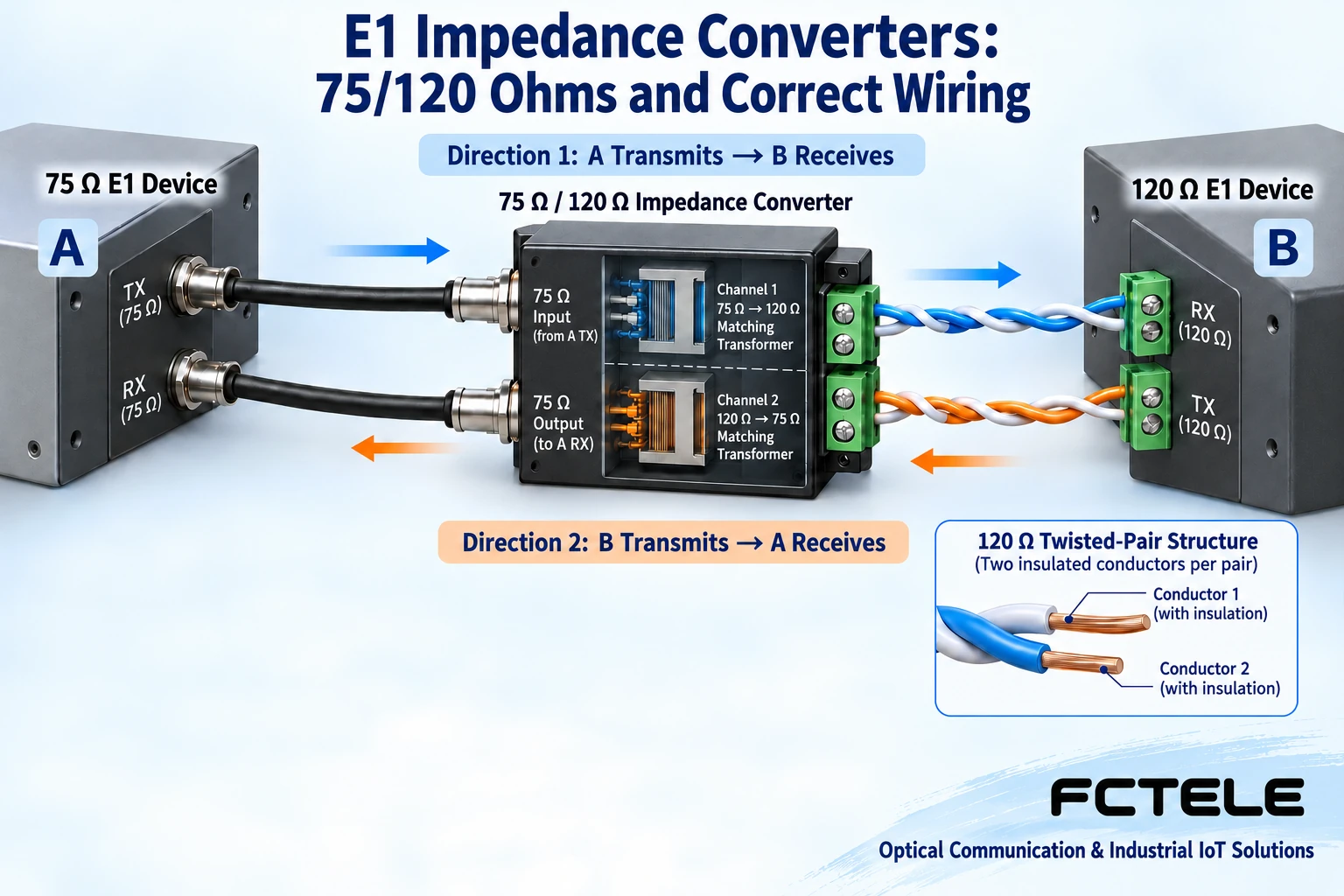
First identify the local TX transmit port and RX receive port in the equipment documentation. One direction should go from device A’s transmit port through the corresponding conversion channel to device B’s receive port; the reverse direction goes from B’s transmit to A’s receive. The 75Ω side usually has separate coaxial connections for receive and transmit, and the 120Ω side usually has separate wire pairs for receive and transmit. The figure uses two directions to explain the relationship; the terminal arrangement of an actual product cannot be guessed from the figure.
Multi-channel rack products require further checking of channel numbering. The first E1 service should go through its corresponding conversion channel to the corresponding service at the far end, not mix sixteen channels into one line. Cable labels should record the device name, channel number, and direction, and after connecting one, confirm it according to plan. Mark unused channels separately from activated channels to avoid treating an empty port state as a fault on a running line.
5. Choosing single-channel, 16-channel, or 24-channel with Feichang Technology products
The public Feichang Technology FCCZ-E1-BNC product is a single-channel E1 75/120 impedance converter, providing the corresponding 75Ω and 120Ω interfaces and requiring no external power. It suits a small number of line handovers or per-channel adaptation. When selecting, understand a single channel as one complete E1 service channel, and at the same time check connectors, transmit/receive relationships, and matching cables; do not infer the number of service channels merely by counting panel jacks.
When a central equipment room has multiple lines, the documented purposes of FCCZ-E16-BNC and FCCZ-E16-L9 are both 16-channel E1 impedance conversion, and one of the main differences is the BNC or L9 connection form on the 75Ω side. Which connector the existing coaxial cables and patch panels use will affect installation convenience and maintenance methods. Neither can be inferred from its name to be an Ethernet switch or E1 multiplexing equipment, and the channel count is not a rate multiplier for any one channel.
The model marked on the official 24-channel product page is FCCZ-E34-BNC, and the product description is conversion of 24 75Ω E1 interfaces to corresponding 120Ω interfaces. The model text and channel count are not a simple one-to-one numerical relationship, so order by the complete product name, ordering number, and confirmed specifications; do not write 34 channels just because you see E34. If spare space or future expansion is needed, record the currently used quantity, reserved quantity, and port correspondence table, then confirm installation conditions and matching cables.
For example, if one end provides eight 75Ω E1 channels and the other end needs eight 120Ω E1 channels, per-channel adaptation and a centralized rack solution can be compared; the example explains the selection method and is not an actual customer case. First confirm that the E1 services, clocks, and electrical interfaces on both sides are compatible, then arrange conversion according to eight complete service channels. Product environmental specifications and other specifications must be checked against current ordering documentation; parameters from single-channel and 16-channel pages cannot be combined into the same device.
6. How to accept the work after connection
In an approved maintenance window, first do a short-cable baseline: use confirmed cables, interface methods, and adaptation channels, and confirm the configuration at both ends and the clock relationship of the test instrument. After the short cable is normal, connect the formal patching and on-site cables, check both directions channel by channel, and record configuration, test conditions, duration, and error results. Test loopback will affect services and should be operated by maintenance personnel according to the manual; after finishing, exit loopback and restore the formal connection.
If no signal is received at all, first check whether transmit exists, whether the receive direction and wire pair are correct, and whether the connectors are reliable, then check the interface selection. If synchronization is possible but there are intermittent errors, compare the short cable with the formal line, different channels, and different directions, and inspect cables, terminations, shielding, clock, and receive conditions. A lit lamp can only be a partial status clue; it cannot replace bidirectional service transmit/receive and error observation, nor can it prove that all sixteen channels are running normally at the same time.
The final delivery should retain the model and version, channel mapping, interface methods on both sides, wiring definitions, cable labels, test results, and restoration records. The value of an E1 impedance converter is to correctly connect different electrical interfaces, not to promise zero errors, any distance, or universal signal enhancement. Confirm physical matching and service configuration separately, and problems become easier to locate, while expansion and maintenance also become clearer.
Sources: ITU-T G.703 digital interface specifications ; Feichang Technology FCCZ-E1-BNC ; FCCZ-E16-BNC ; FCCZ-E16-L9 ; official 24-channel product . This article does not derive unverified parameters from suspected official website entry errors; ordering specifications are subject to confirmed documentation. The principle diagrams are general mechanism illustrations, not physical objects, measured waveforms, or certification proof.
Related topics: How to read parameters of an 8E1 PDH optical multiplexer: eight services, impedance, and matching interfaces .
Common on-site questions
If a multimeter cannot measure 75Ω on an E1 cable, is the cable unqualified?
It cannot be judged that way. 75Ω describes the characteristic impedance of the transmission line, not the DC resistance of the conductor; a multimeter continuity test also cannot prove high-speed pulse quality. First check the cable and termination specifications, then inspect with a suitable E1 interface and test method. Do not randomly add components in parallel on the signal line just to make a resistance reading.
Can a passive E1 impedance converter amplify signals and recover the clock?
It cannot be considered to have these capabilities. Common passive magnetic conversion is used to adapt balancing method and impedance conditions, and it still has insertion loss; it is not equivalent to active regeneration or retiming. Frame, timeslot, and system clock conflicts will not be automatically repaired by it either. After connection, verify the complete line rather than assuming that adding an adapter will necessarily improve all errors.
For one bidirectional E1 service, if only one TX to RX is connected, why can only one direction pass?
Transmit and receive are two directional paths, and the TX at each end needs to reach the RX at the other end, with the specific wire order according to the interface definition. BNC, L9, and RJ45 shapes cannot replace pin checking. Multi-channel equipment must also mark the correspondence channel by channel; the model number does not necessarily equal the actual channel count, and it should be confirmed with current product parameters and ordering configuration.
Continue reading: How to troubleshoot E1 impedance mismatch: reflections, pulse decision, and error acceptance ; How to judge interface compatibility of a PDH optical multiplexer: E1, Ethernet, and optical side formats ;
Translated from the Chinese technical article. Source first published: 2024-09-24. Source last revised: 2026-10-15T22:31:43.863560+08:00. Read the Chinese source
