


A managed industrial switch having a monitoring menu does not mean on-site faults can be automatically located. Truly effective monitoring should leave mutually verifiable evidence at three locations: the device, the line and the service. During acceptance, you must prove that the traffic that should be seen can be seen, the events that should be reported can be received, and service interruption and recovery can be independently measured, rather than just taking a screenshot of a green topology.
1. First clarify what monitoring actually observes
The switch hardware is responsible for receiving and forwarding Ethernet frames; a frame is the data unit transmitted on a link. The management program reads port status, error and discard counters, and then provides the results to maintenance personnel. Services may still be forwarding, but the management computer temporarily fails to access due to address, access rules or management load. Therefore, if the management page cannot be opened, you cannot directly conclude that the switch has stopped working.
Before acceptance, write down the service source, destination device, port, associated virtual local area network and expected path. A virtual local area network is VLAN, used to divide the Layer 2 broadcast range; configuring a VLAN itself does not automatically connect different network segments. The network diagram should also note link speed, optical modules and backup paths. Automatic topology discovery requires the model and adjacent devices to support the corresponding discovery mechanism; a missing node on the diagram may simply be insufficient discovery capability.
2. Mirroring sends a copy to an observation point
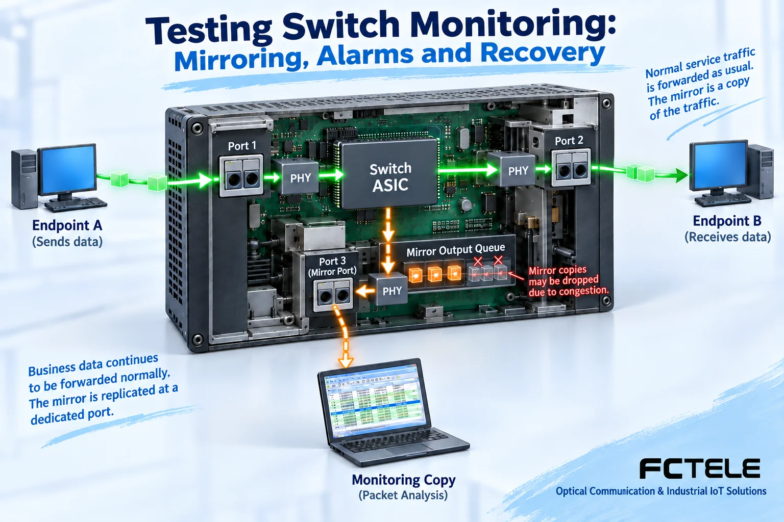
A unicast frame that has already learned the destination address is usually sent directly to the corresponding service port. Plugging a laptop into another port at random does not necessarily allow you to see this communication. Port mirroring, however, copies the traffic of a specified ingress or egress according to configuration and sends it to a dedicated observation port. Ingress means entering the switch, egress means leaving the switch; choosing the wrong direction, port or VLAN will make the capture result incomplete.
First, in an isolated test, send known traffic with sequence numbers, confirm what the service receiving end receives, and then compare it with the mirror capture. After multiple source traffic streams are aggregated, they may exceed the processing capacity of the mirror port or the capture computer; the copy queue, network card, software and disk also have their own limits. Missing packets in the mirror do not mean missing packets at the service receiving end, and capturing complete data does not guarantee that other services are normal. Whether mirroring affects forwarding is also related to hardware architecture and configuration, and it cannot be promised that all models are completely unaffected. For related boundaries, refer to Cisco’s SPAN description , and specific operations must use this device’s manual.
The observation location also determines how to interpret the quantity. If you mirror both the ingress and egress of a frame at the same time, two copies of this frame may appear in the capture; this does not necessarily mean the production network really sends duplicates. You should record the capture direction, source port and filter conditions, and use test sequence numbers to verify the copy relationship. The time recorded by the capture computer is the time of arrival at that observation point, and cannot be directly taken as the time the service end receives it. If the filter is set too narrowly, or the capture network card cannot interpret a certain type of tag, frames that have already arrived may also fail to appear in the displayed results. First use known test frames to verify the capture chain, then compare before and after the fault using the same settings, so that the evidence is comparable.
3. Alarm effectiveness requires checking both generation and arrival
Polling is when the management system regularly asks the device; active notification is when the device sends out after an event occurs. SNMP is a commonly used management protocol, Trap is one of its event notification methods; Syslog is used to transmit logs. They solve observation problems and do not replace the service receiving end in proving communication quality. When the polling cycle is long, a short fault may occur between two inquiries; when the notification transmission path is interrupted, the device has an event record, but the remote end may also fail to receive it.
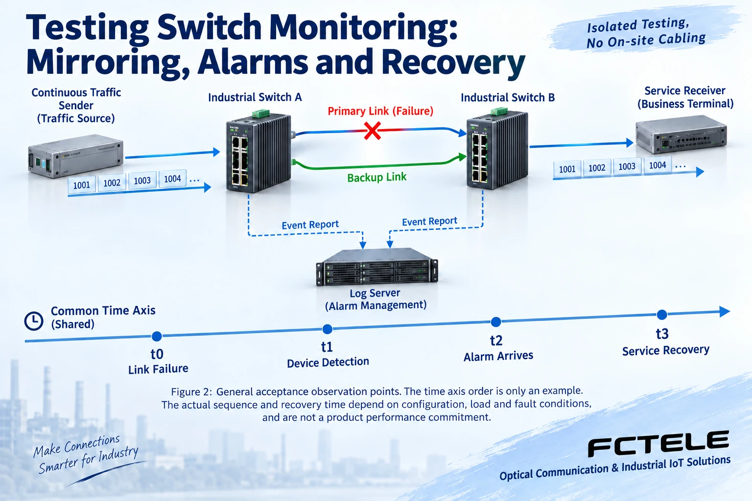
First calibrate the time of the device, log server and test tool, and record their synchronization method and accuracy. Generate a controllable event using the method allowed by the model, and verify the device local log, server receipt time, event object and recovery record. Then check access permissions, receiving address and network rules. To test alarms, do not randomly unplug cables, cut power or create broadcast storms on the production network; use an isolated environment and a pre-approved test window.
4. Recovery time must be measured from the service observation point
A redundancy protocol detecting a fault and reselecting a path is not the same moment as the terminal resuming continuous sending and receiving. The port light turning on again, or the network management receiving a recovery notification, only indicates that the corresponding observation point has changed. From this, you cannot write all ring networks as fixed less than fifty milliseconds, and even less can you equate recovery with no packet loss.
In an isolated bench, continuously send test traffic with time and sequence numbers, while recording fault triggering, device detection, alarm arrival and receiving-end recovery. The test plan should specify frame length, load, fault location and the criterion for “recovery”, for example the receiving end again continuously receiving a specified number of valid frames. Repeat tests at different locations, recording the interruption interval, missing sequence numbers and duplicate frames. Alarms may be earlier or later than service recovery, and original records must be kept; you cannot just copy the minimum value.
5. Turn Feichang Technology product functions into acceptable items
Feichang Technology M12 interface sixteen-port gigabit managed switch product page lists mirroring, Syslog, RMON, Trap and ring network related functions. They respectively provide traffic copies, logs, remote monitoring and event notification. When purchasing, you should require clear software version, monitorable objects and limits. The product page listing functions does not prove that the same recovery time is achieved under any wiring and load, nor can it replace actual network acceptance.
Delivery records should at least include model and version, configuration backup, test topology, test conditions, original captures and logs, abnormal phenomena and retest results. After exporting the configuration, also confirm the recovery method, and do not treat “having a backup file” as proven ability to recover. Limit remote management permissions; mirror data may contain on-site service information, so collection should be authorized and properly stored.
The end point of acceptance is not discovering that all menus exist, but that maintenance personnel can reproduce problems, explain observation results, and know what the evidence cannot see. First determine whether the service is affected, then use mirroring, counters and logs to narrow the scope, so that the limitations of the monitoring tool itself are not misjudged as a switch fault.
Material note: Product capabilities are subject to the above Feichang Technology models and actual versions; the SPAN material is used to explain the observation mechanism and is not the basis for Feichang Technology commands or performance. The illustrations are general principle diagrams, not actual product photos or measured records.
Common on-site questions
If the mirror capture is missing data, can it prove that the switch dropped production packets?
No. The mirror port, copy queue or capture computer may reach capacity limits first, and direction and filter settings also affect the result. You should compare the actual received result with sequence numbers against the mirror copy, and record the observation location. Capture loss and service loss are two judgments, and one cannot directly replace the other.
The device has a local link-down log, why did the network management not receive a Trap?
Local event generation and notification arrival at the remote end are different stages. You also need to check notification settings, receiving address, permissions and transmission path; the fault itself may interrupt that path. Synchronize the time of each observation point, and under controlled conditions compare local records, server receipt and recovery events. Do not directly equate not receiving a notification with no fault occurring.
The port recovery notification shows 20 milliseconds; can the service recovery time also be filled in as 20 milliseconds?
It cannot be directly carried over. Port, protocol detection, alarm transmission and the application continuously receiving valid data have different observation boundaries. You should use test traffic with time and sequence numbers, record the fault trigger and receiving-end recovery criterion, and explain the load and measurement resolution. Keep multiple results, and do not select only the shortest one as a commitment for the entire network.
Continue reading: Advanced configuration of managed industrial switches: QoS, multicast and security policies ; How to do network redundancy: detailed explanation of backup paths, dual machines and fault domains ;
Translated from the Chinese technical article. Source first published: 2024-08-21. Source last revised: 2026-10-15T22:31:43.863560+08:00. Read the Chinese source
