


Conclusions first
Purpose first: let a USB-only computer connect to a serial device
A computer has only USB ports, but an instrument provides RS232 or RS485. A USB to serial converter can move data between the two interfaces. The computer accesses the serial port through a matching driver, and the converter sends the received bytes to the instrument according to the settings; the instrument’s reply then returns to the computer through the converter. It adds a connection method, and the instrument still works according to its own commands and parameters.
A converter is not an adapter that simply turns a USB plug into a few wires. USB has device identification, transmission organization and power supply conditions, while serial ports have independent character formats and electrical requirements. A correct solution requires a bridge circuit, and also requires correct software, interface and wiring. Seeing the device light turn on or a COM port appear only completes part of this path.
The COM port is the software entry point; a USB device must first be identified
A COM port can be understood as the entry point through which an application reads from and writes to the serial port. After a USB device is plugged in, the system reads its description information and then loads a driver for the matching device. Products using a virtual COM driver provide one or more serial port names; the computer does not thereby gain a traditional serial hardware port, and data still passes through USB transmission.
The system’s built-in USB serial driver can automatically match the corresponding CDC device class, but it cannot be assumed that all USB to serial converters are driver-free. Different bridge chips, hardware versions and operating systems may require the corresponding manufacturer driver. An application may also use a dedicated interface rather than a virtual COM port. Before use, confirm according to the product version, and do not casually install drivers with similar names.
When sending, USB transmission and UART each complete one step
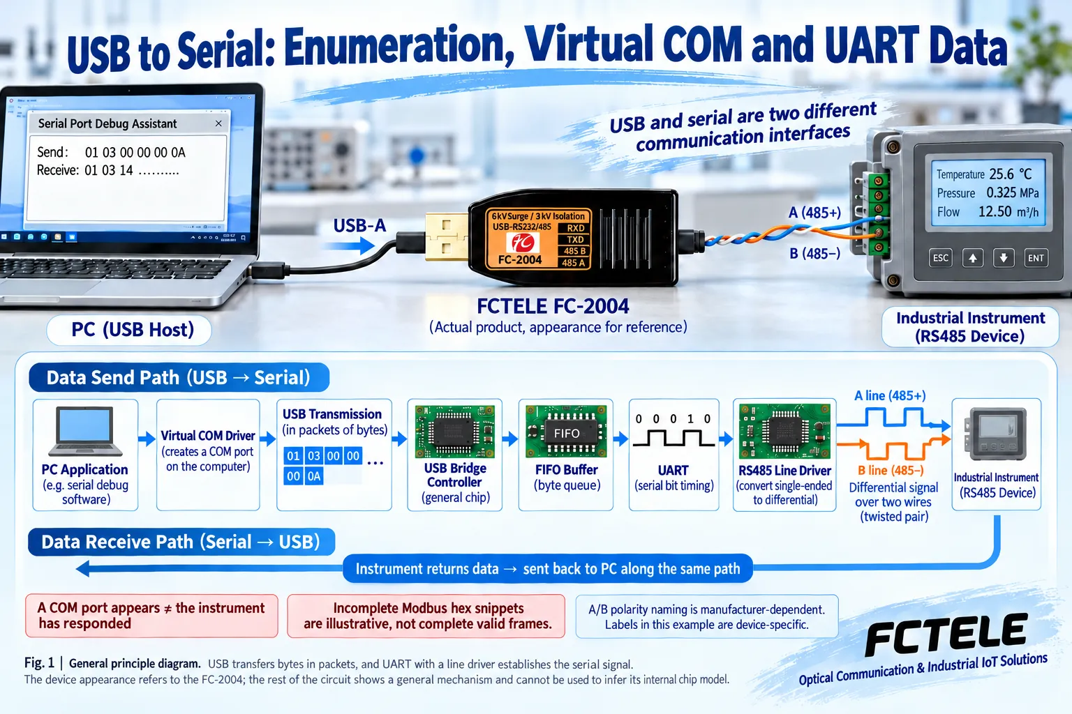
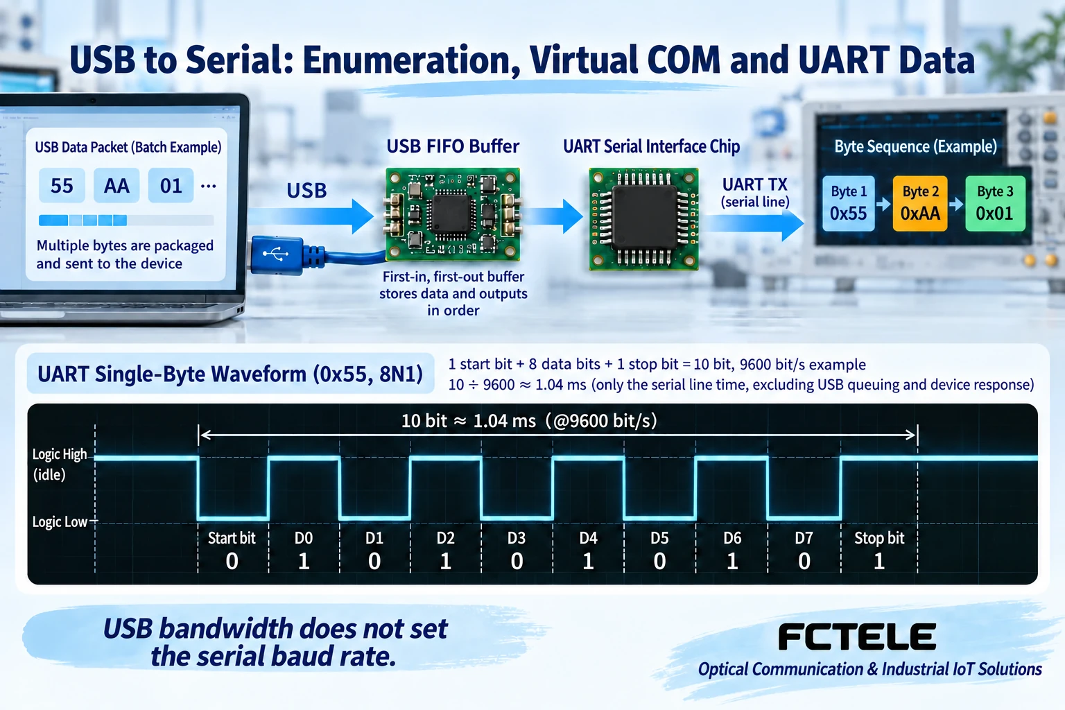
After software writes a string of bytes, the driver and USB transmission send them to the converter. The bridge circuit recognizes the transmission, the bytes enter the buffer, and then the UART sends them in sequence according to the configuration. UART is a universal asynchronous receiver/transmitter circuit. It is responsible for arranging bytes into a serial format with start, data, parity and stop information, and which parts are present is determined by the settings.
The buffer is like a temporary queuing area. It can coordinate the rhythm between USB arriving in batches and the serial port sending bit by bit, but its capacity is limited. If software keeps writing faster than the line sends, the queue may build up. USB messages, UART characters and one application command from an instrument are three different boundaries, and one software write does not necessarily correspond to one complete instrument response.
UART logic signals must also become the correct line levels
The internal output of a UART is often a chip logic level and cannot be used directly as an RS232 or RS485 interface. RS232 requires corresponding level driver and receiver circuits; RS485 requires a differential transceiver and uses the voltage difference of the wire pair to transmit information. Isolated products may also add signal and power isolation along this path, and the specific internal implementation varies by model.
Therefore, the connector shape cannot replace the electrical standard. Terminals marked TXD and RXD may belong to TTL or to RS232, and they cannot be interconnected just because the names are the same. Plugging into the wrong electrical interface may prevent communication and may also damage equipment. The bare chip in the figure is an illustration of a general mechanism, not an actual teardown or pin diagram of a Feichang Technology product.
When receiving, data returns to the application in the opposite direction
The serial line signal output by the instrument is first recognized by the receiving circuit. The UART restores bytes according to settings such as baud rate, data bits and parity, then they enter the receive buffer and return to the system and application through USB. Some abnormalities may appear as character format errors, parity errors or lost data, but which errors can be reported specifically depends on the driver and hardware capabilities.
After the application receives bytes, it must also verify whether the message length, checksum, address and command are correct. For example, Modbus RTU fields and checksums require corresponding software processing. An ordinary USB serial bridge will not automatically translate any instrument protocol into another protocol. It also will not automatically turn an old device into a network server or allow multiple computers to control it at the same time.
Baud rate limits still remain; USB bandwidth cannot replace them
Using the common 9600 bit/s, 8N1 as an example: each character contains 1 start bit, 8 data bits and 1 stop bit, for a total of 10 bits. One byte on the line takes about 10 divided by 9600, which is 1.04 milliseconds; 100 consecutive bytes take about 104 milliseconds. This is only the line-speed time to send these characters, and does not include command intervals, USB queuing or device processing.
Even if the USB side can transmit more data, the instrument still receives at the set serial rate. Increasing the baud rate also requires support at both ends and re-verification of cables and on-site conditions. Serial refresh is also affected by instrument response, bus scheduling and software timeout. The chip’s maximum capability, the range published by the product, and the rate that can be stably used in this project cannot be treated as one number.
Feichang Technology FC-2004: one serial task, choose the corresponding interface
FC-2004 in the product center provides USB to one channel of RS232 or RS485. Public information states that the two interfaces cannot be connected and used at the same time, and the converter body is powered by USB. It is suitable for temporary computer debugging or connecting one corresponding interface task. The two interfaces cannot be understood as two independent COM ports, nor can two devices with different interfaces be connected at the same time on this basis.
The information for this model separately lists the applicable rate ranges for RS485 and RS232, and explains serial isolation, line protection and transmit/receive indication. When selecting, check the range, driver and terminals of the delivered version according to the interface used, and do not apply the RS485 upper limit to RS232. So-called automatic transmit/receive also does not mean there is no delay in all transmission stages, and the complete response still needs to be verified.
To debug TTL devices, choose a corresponding USB to TTL product
If an embedded board provides a TTL serial port, confirm the logic voltage and allowable input range, then choose the corresponding converter. Feichang Technology FC-2009 is clearly identified in the product center as USB to TTL and can serve as a selection entry point for this type of task; its purpose differs from the RS232/485 of FC-2004, and it cannot be used as a replacement merely because it also has TXD and RXD.
Power terminals and signal terminals should also be viewed separately. The converter can obtain its own operating power from USB, but this does not mean it can supply power to any external board or instrument. It can be used only when the model truly provides an auxiliary output and the voltage, power and terminal conditions match; when the external device already has a power supply, it is also necessary to check whether connecting another power source is allowed.
Using one instrument as an example, verify the data path at each stage
Assume the task is to use a computer to read an RS485 instrument. First confirm the instrument protocol, address and actual parameters such as 9600, 8N1, then choose the corresponding converter, install the matching driver and record the COM number. After powering off, check the wiring and power supply, then use the correct software to send a known query and confirm that what returns is new data from the target instrument, not just a value already displayed by the software.
If the COM port does not exist, first check the USB cable, identification and driver; if the COM port exists but there is no reply, then check port occupation, interface, wiring and protocol parameters; if there are bytes but parsing fails, check the character format and message checksum. Change only one condition at a time and keep records of sending and receiving to determine which stage the problem is at.
Acceptance should prove the real application, not just that it can be plugged in
Under a representative load, observe continuous reading, reconnection and recovery, and check whether the COM mapping is stable, whether data updates in time, and how timeouts and errors are handled. Multiple serial ports, long lines and on-site interference require additional design, and the successful result of one short-line instrument cannot be directly extended to all scenarios.
Delivery records should include the product model, driver version, COM mapping, serial format, protocol, wiring and power supply, as well as normal response samples. Only when the reader can explain how data changes from software into line signals and how replies come back, and can locate faults by stage, can they truly understand how USB to serial works.
Compare with the actual photos in the product center
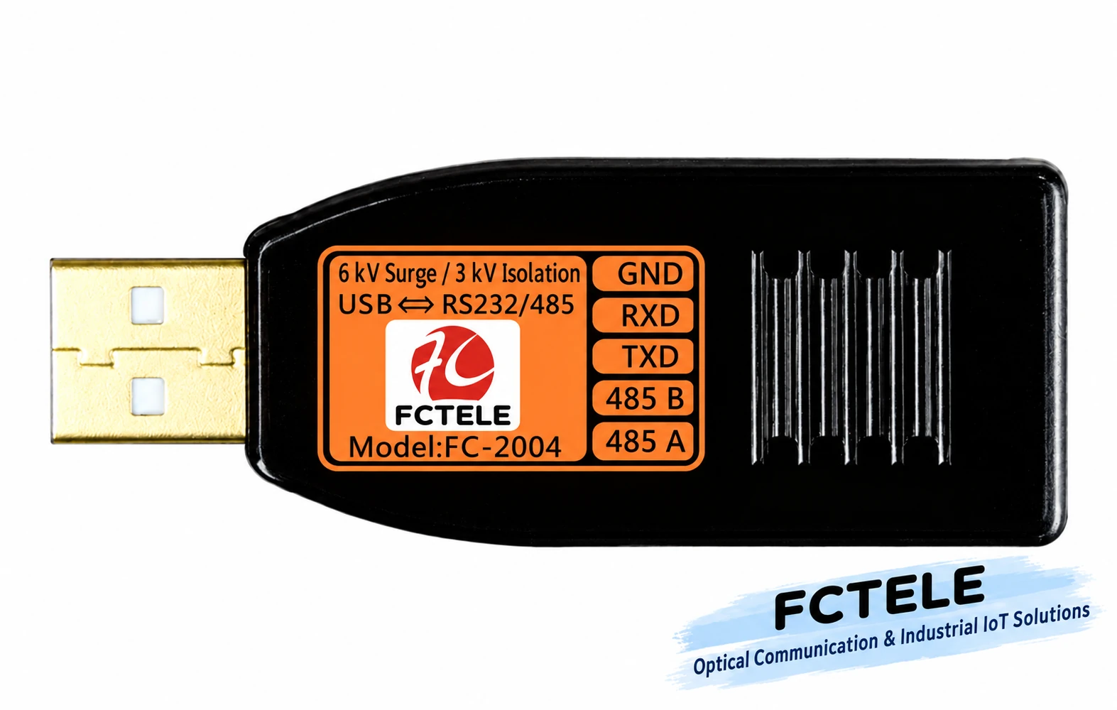
One channel of RS232 or RS485, choose one according to the task. Based on the official product photograph, with label text localized into English; the exterior and model reference are retained.
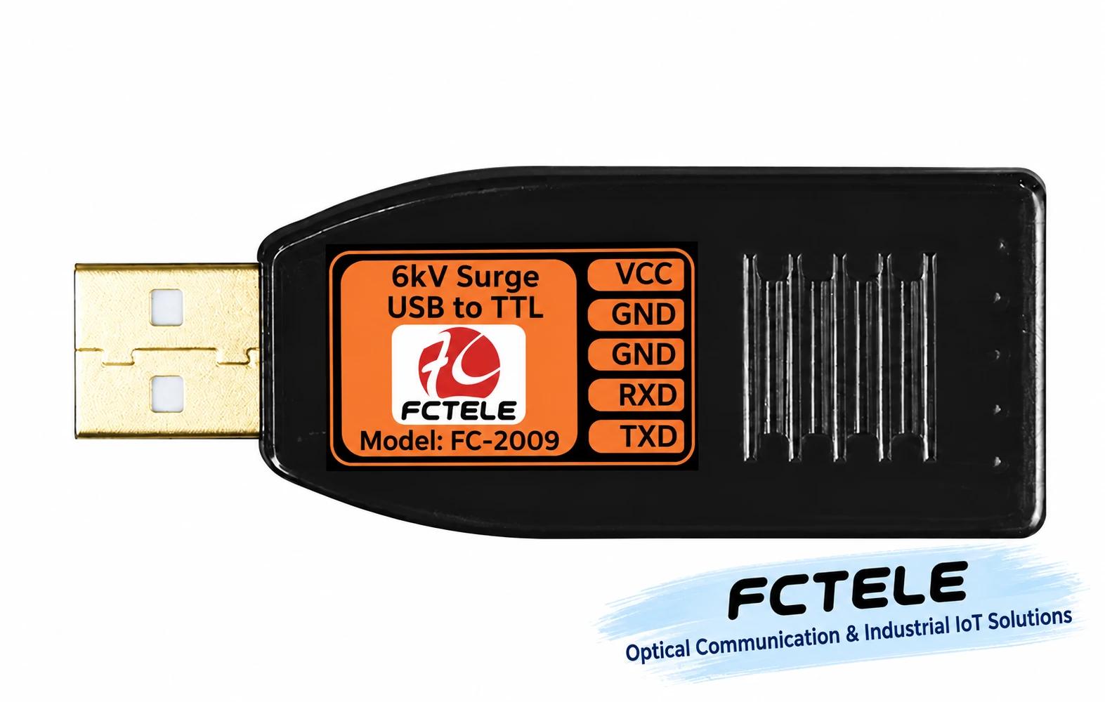
USB to TTL, first check the logic voltage. Based on the official product photograph, with label text localized into English; the exterior and model reference are retained.
Reference note: The illustrations are general mechanism diagrams and have been technically checked; appearances with model numbers are based on official website photos, and other cutaway views and components do not represent the internal circuits of actual Feichang Technology products. They are not measured waveforms or real project sites, and wiring and power supply are subject to the delivery manual.
Verification references: Feichang Technology FC-2004 single-channel RS232/485
Feichang Technology FC-2009 USB to TTL
TI TUSB3410 USB/UART bridge principle
Microsoft serial port parameter configuration
Microsoft USB serial driver matching
Common on-site questions
The USB interface rate is very high, so why does a 9600, 8N1 serial port still transmit slowly?
The serial output is still limited by its own baud rate and character format. At 9600 bit/s, 8N1, each character occupies 10 bits, and 100 consecutive bytes take about 104 milliseconds on the line, not yet counting USB scheduling, processing and response waiting. This is a calculation under specified conditions, not a product measurement; switching to a high-speed USB socket will not automatically increase the serial rate supported by the instrument.
Can a USB to TTL cable connect to an ordinary RS232 device?
It cannot be directly interconnected just because both have TX and RX. TTL and RS232 differ in electrical levels and interface conditions, and TTL also requires confirmation of the specific voltage and tolerance. First check the terminals, levels and exact adapter model on both sides. Similar signal names and connectors do not mean compatibility, so avoid judging by repeated trial connections.
If one converter supports RS232 and RS485, does that mean it is two serial ports that can be used at the same time?
Not necessarily. It may be the same UART selecting different electrical interfaces, or it may be multiple independent channels, and this should be confirmed according to the specific product definition. The two interface names cannot be added together as the number of concurrent channels. When purchasing, list the number of devices working simultaneously, the interfaces and driver requirements, then check the actual port mapping and test.
Continue reading: How to choose USB to serial? Feichang Technology single-channel, multi-channel and isolated power supply solutions ; How to use USB to serial? Drivers, RS232/485 wiring and transmit/receive troubleshooting ;
Translated from the Chinese technical article. Source first published: 2024-09-12. Source last revised: 2026-10-15T22:31:43.863560+08:00. Read the Chinese source
