


DYING GASP, AT A GLANCE
How can a device notify you as power disappears?
A purpose-designed device may use stored energy to detect input failure and send a final notification before essential circuits stop. The processor, transmit circuitry, path and receiver must all be available for the intended operation. Notification behavior depends on the implementation. Dying Gasp provides a diagnostic clue, not a promise of continued service or guaranteed delivery.
Preserve essential energy
A final action needs a designed hold-up window. An ordinary capacitor does not prove notification support.
Identify the recipient
Verify the actual OAM or management behavior. Do not assume a link-local indication crosses the whole network.
Keep the observer available
An intact communications path and a powered receiver are part of the evidence chain.
Verify the implementation
Check the selected hardware, firmware, trigger conditions and notification method.
Verify the whole path
Identify the adjacent peer, management route, recorder and each supply source.
Verify the evidence
Separate final transmission, reception and later service recovery in an approved test.
Selection and verification checklist — expand
| Check | What to confirm | How to verify |
|---|---|---|
| Energy | Designed hold-up for essential circuits | Use selected documentation, not capacitor presence alone. |
| Trigger | Input failure, reload or other conditions | Read event definitions and correlate logs. |
| Recipient | OAM peer or management destination | Verify both sender and receiver capabilities. |
| Path | Power and communications remain available | Map shared supply and common fault points. |
| Recovery | Restart and ordinary service return | Record startup events separately from the final alert. |
Conceptual illustrations, not measurements, modification instructions or claims of model-specific Dying Gasp support.
Why can a monitoring system sometimes receive a power-loss notification after a device power connector has been unplugged? The device is not communicating without energy. A small amount of stored energy may remain after the input supply disappears, allowing a brief operation. Dying Gasp commonly describes a final notification before the device stops. It can help explain a failure, but does not guarantee that service continues.
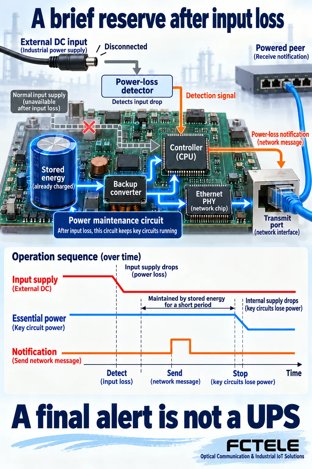
Input loss and complete internal power loss are different moments
Inside a network device, power conversion and regulation supply the processor, switching logic and transmit/receive circuits. A capacitor stores energy while power is available and can release it briefly after the input falls. A water tank is a useful analogy for a little supply remaining after the source stops, but a circuit must also meet voltage and load requirements. It cannot necessarily keep operating until the stored energy is completely exhausted.
A purpose-designed hold-up circuit can create a short window between input failure and the point where essential circuits can no longer operate. That window supports a specified action rather than normal full-device throughput. The presence of an ordinary filtering capacitor does not establish Dying Gasp support: energy storage, conversion and software must all meet the intended design.
The TI application note on backup power for Dying Gasp illustrates a design approach using supercapacitor energy and power-conversion circuitry. This article explains the general process without treating that evaluation design measurements as FCTEL product specifications or assigning one universal hold-up duration to every switch. Load, temperature and component condition can all affect the available window.
Detect the supply decline before arranging the final action
Preparation cannot wait until the processor has already stopped. Power monitoring must detect an abnormal input while the necessary internal supply is still valid. An interrupt handler or dedicated logic can then begin the final operation. An interrupt is like an urgent hardware request for attention, allowing the processor to handle the event rather than waiting for an ordinary task to reach it.
Control logic next forms the notification according to the implementation and maintains the required transmit path long enough for the intended action. If the processor still has power but the port circuitry has stopped, the message cannot leave. Conversely, a powered port cannot invent a meaningful alert if no message was prepared in time. Detection, processing and transmission must work together.
This is why simply attaching a large capacitor in the field does not establish Dying Gasp support. Extra storage can affect charging current, protection and startup behavior, and the software may not recognize input failure. Verify the original design and the selected version documentation rather than treating this conceptual explanation as a modification or wiring guide.
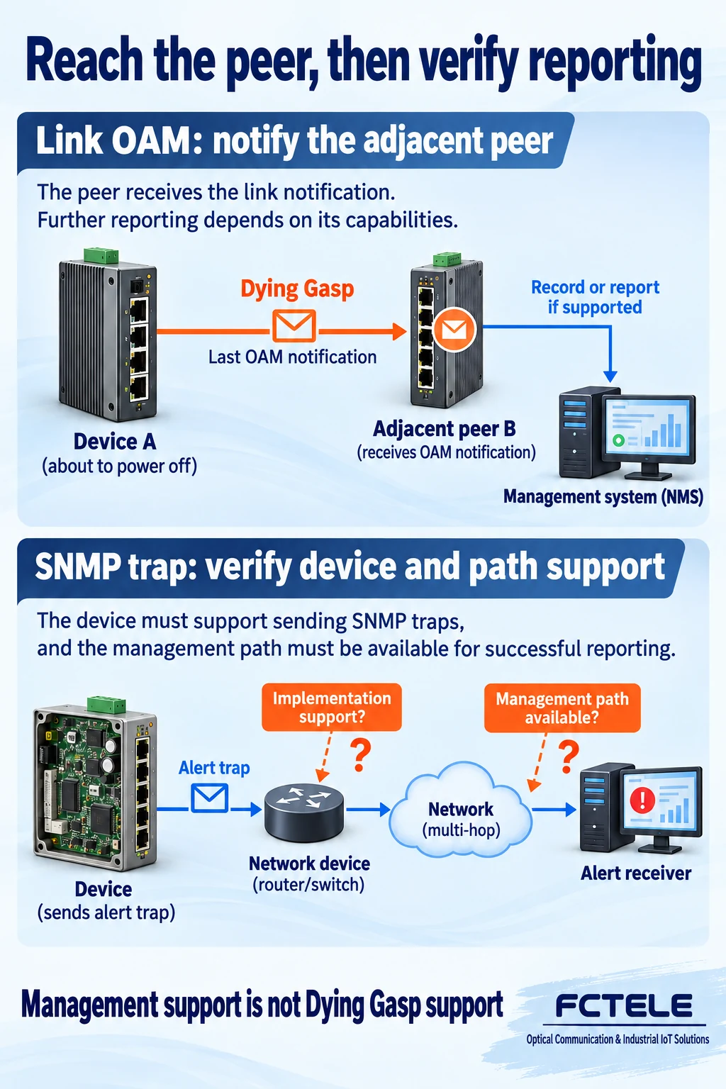
Who receives the final notification?
Ethernet OAM refers to operations, administration and maintenance mechanisms. A link-OAM indication of a dying-gasp or unrecoverable state is first directed to the adjacent link peer. That peer records, presents or reports the event according to its implementation. Do not assume that a link-local OAM indication travels unchanged through every intermediate device to a distant server like ordinary application traffic.
Some implementations also provide management notifications such as SNMP traps. A trap is an event message sent proactively to a management system, unlike a manager periodically polling for status. However, SNMP support alone does not prove that a device can send a trap during power loss. The recipient, trigger conditions and transmission capability must be verified separately.
The referenced Cisco guide identifies selective platform support and particular transmission behavior, illustrating that capabilities and restrictions depend on implementation. Dying Gasp should not universally be equated with unplugging the power supply: some implementations include reload or interface shutdown among related unrecoverable conditions. Read the event definition and surrounding logs before interpreting an alert name.
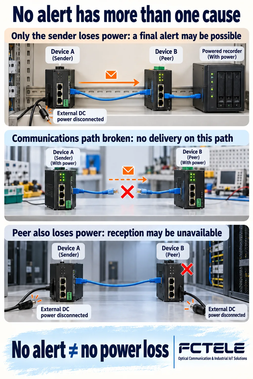
Why support does not guarantee reception
A final notification still needs a working path. If the neighboring switch loses power at the same time as the sending device, it cannot receive the indication. If the monitoring system shares the failed supply, it may not retain a record even when the field device had time to transmit. Sender capability does not establish receiver availability across the complete monitoring chain.
Unplugging a communications cable, breaking an optical path and removing device power are different conditions. Once the transmission path is already broken, expecting an alert to arrive through that same path is not valid. Queueing, processing timing and configuration can also affect transmission. Absence of a notification is therefore an observation to investigate, rather than proof that power loss did not occur.
Draw the sender, adjacent peer, management path and recorder together, and mark each supply source. If records originate from different devices, verify whether their time references are comparable. Otherwise a notification displayed later could be interpreted as an event that occurred at a different time, confusing the sequence of the incident.
Separate Dying Gasp, redundant inputs, a UPS and alarm contacts
Redundant power inputs aim to let another supply take over under the design conditions and reduce service interruption. Dying Gasp instead leaves a clue as operation is about to stop. A UPS provides backup energy for continued operation or an orderly shutdown. These capabilities can complement each other, but a final notification is not a backup power source and two input connectors do not prove Dying Gasp support.
A relay alarm contact provides a different detection path by changing an electrical contact state for another device to observe. Verify the contact meaning, its normal and unpowered states, and the external input system power. It does not inherently carry a complete network event. This general distinction does not mean every FCTEL switch has the same contacts or supports an identical event set.
If one redundant input fails while the other continues supplying the unit, the device may report an input fault without entering a final-shutdown process. Separate a single-input failure from complete device power loss before acceptance testing. Define which condition must be detected, then establish which output the selected device actually provides.
Use published product information to ask precise questions
The FCTEL page for the mini DIN-rail five-port Fast Ethernet switch describes supply options and redundant power inputs. That information helps identify power configurations, but does not establish Dying Gasp, a particular OAM indication or a power-loss trap. Confirm the model, hardware configuration and firmware together. This article does not add capabilities that the published information does not establish.
Ask concrete questions: Is there dedicated power-loss detection and hold-up circuitry? Which final notification is supported? Does it notify an adjacent peer or send directly to a management address? Must OAM be enabled? What must the receiver support? Under which conditions was the behavior verified? These questions produce more testable requirements than simply asking whether alarms are available.
Also establish the trigger scope. Are single-input failure, complete power loss, software reload and interface shutdown reported separately, and can the event names distinguish them? A management system should interpret the information the device actually provides rather than reducing every abnormal condition to one red offline icon. Define where and how long records must be retained.
Verify three different faults under controlled conditions
Use an isolated bench or an approved maintenance window. Save the configuration and establish that ordinary communications, event reception and recording work. If the product documentation declares the relevant notification, test power loss in the permitted way and record what the adjacent peer observes, what reaches the manager and how service subsequently stops. Do not casually remove power from an operating critical control network.
Separately test permitted conditions such as communications-path interruption or loss of only one redundant input. Match logs to operation times. Changing one condition at a time helps distinguish an input fault, a broken link and a stopped device. One successful final notification does not prove delivery for every possible power-loss sequence.
After restoring power, confirm normal startup, service recovery and any separate startup event. Record final transmission, reception at the collector and service restoration as three different outcomes. Dying Gasp contributes a conditional piece of diagnostic evidence; it does not replace supply design, fault localization or recovery verification.
Sources and product evidence
TI: Supercap Backup Power for Dying Gasp Application, April 2026; Cisco: Dying Gasp Through Ethernet OAM, updated April 28, 2026. These sources support general mechanisms and implementation differences; their device parameters are not FCTEL specifications.
Published product evidence: FCTEL mini DIN-rail five-port Fast Ethernet switch, Chinese-language page. Verify the selected power configuration and notification capability against the specific version documentation. All illustrations are generic concepts made with AI assistance.
Translated from the Chinese technical article: Read the original Chinese article.
Common practical questions
Does a capacitor guarantee Dying Gasp?
No. Detection, short-term power, processing and the transmit path must work together. An ordinary filtering capacitor does not establish support for a final notification.
Does no final notification rule out power loss?
No. Simultaneous receiver power loss, a broken path, configuration or an insufficient send window can prevent reception. Correlate power, link and collector evidence.
Can redundant power, a UPS and Dying Gasp replace each other?
No. Redundant inputs address supply takeover, a UPS provides backup energy, and Dying Gasp leaves a clue before shutdown. Verify each capability against the actual requirement.
Scope and further reading
Generic stored-energy and notification-path concepts, not measurements, modification instructions or verified model-specific Dying Gasp support.
Related power and alarm guide · Related network management guide
