


RS485 UNIT LOADS, AT A GLANCE
Why is counting boxes not enough?
RS485 unit loads describe receiver-input burden under specified electrical conditions. Different inputs can consume different shares, so the commonly quoted 32-unit-load budget is not a universal count of enclosures. Add the documented input loading for the same electrical segment, check driver capability and other loads, and verify real communication. A low-load IC does not establish the capacity of every finished product or installation.
Parallel input burden
A listening receiver still presents an electrical load. Adding inputs adds burden.
Check input conditions
One resistance reading does not establish worst-case unit loading.
Separate the other loads
Termination, bias and signal integrity require their own checks.
Identify each input
Record the exact interface model, loading specification and power-state conditions.
Map the electrical segment
Identify shared wires, actual repeaters, termination and bias locations.
Verify the field conditions
Record rate, cable and stubs, timing, and the communication tests actually completed.
Selection and verification checklist — expand
| Check | What to confirm | How to verify |
|---|---|---|
| Inputs | Documented unit-load rating | Read exact equipment and component conditions. |
| Driver | Supported loading and required test conditions | Use the actual driver or finished-product documentation. |
| Other circuits | Termination and bias burden | Map enabled circuits and their stated behavior. |
| Segment | Actual shared electrical pair | Confirm the function of converters and repeaters. |
| Operation | Rate, wiring, timing and power cases | Run controlled application tests and retain the results. |
Generic mechanisms, not a product circuit or measured node-capacity guarantee.
After a few more devices are added to an RS485 bus, communication that was stable begins to fail. Has it exceeded a maximum of 32 devices? Do not start by counting enclosures alone. RS485 uses unit loads to describe the electrical burden that connected circuits place on a driver, and different receivers may consume different shares. Knowing who supplies current and who uses driver capability helps explain the conditions behind node-count claims.
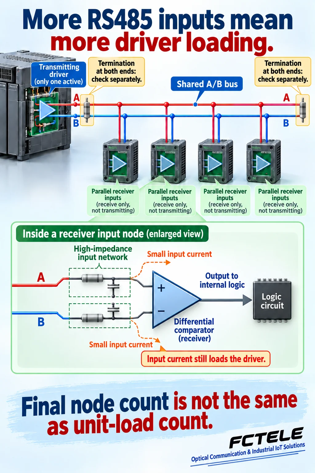
Receiver inputs on the same pair are connected in parallel
In a common two-wire, half-duplex RS485 link, several devices share the A and B signal conductors. When one node takes its turn to transmit, its driver establishes a voltage difference between the wires. The other receiver circuits observe that difference and pass the signal to their digital logic. These are signal roles, not a universal rule for every manufacturer’s A/B polarity naming.
A receiver mainly listens, but it does not leave the bus completely untouched. Its input circuit presents input current and impedance to the lines. Adding an input adds another parallel burden alongside the existing ones. Individually small burdens are not necessarily negligible in combination. The transmitter faces the loading of the entire electrical bus segment.
Think of the driver as a supply maintaining water pressure and receiver inputs as small branches connected to it. This analogy only explains how parallel burdens accumulate. Data is not conveyed by water consumption: actual communication depends on voltage changing over time and receivers distinguishing states at the right moments.
A unit load is a common scale, not another name for a device
RS485 uses the unit load, abbreviated UL, to compare the steady-state input burden of connected circuits under specified conditions. It is a common measuring scale rather than a count of enclosures. One node may present one unit load, while another may use only a fraction of that amount.
Engineering references commonly relate standard driver capability to 32 unit loads while also specifying test conditions such as termination. The number 32 describes an electrical loading budget. It does not mean a protocol must reject address number 33. RS485 itself does not define one universal application address table imposing the same device count on every installation.
Values such as one-half, one-quarter and one-eighth unit load describe a receiver input’s share of the common scale. They do not mean a device receives half a byte, nor that its data rate changes in the same proportion. First establish whether a parameter concerns input circuitry, software addressing, station management or overall product capacity.
Why one multimeter resistance reading cannot settle the question
Unit loading concerns input-pin current over a specified voltage range. Receivers contain input networks, protection and bias circuitry that may not be represented completely by one constant resistor. Equivalent resistance is useful for explanation, but that simplified model is not automatically a drawing of the actual internal wiring.
TI’s technical explanation emphasizes checking input current over the specified range and examining relevant pins in powered and unpowered states. The reason is straightforward: the voltage relative to the receiver’s reference can change, and so can internal circuit states. A small current at one voltage does not establish that the worst-case burden is equally small under other conditions.
This is an approach to evaluating devices and verifying documentation, not an instruction to apply test voltages to an operating production bus. Start with the exact model, revision, receiver input specifications and manufacturer limits. If the only information is a resistance without conditions or a chip-family name, leave the loading conclusion unconfirmed.
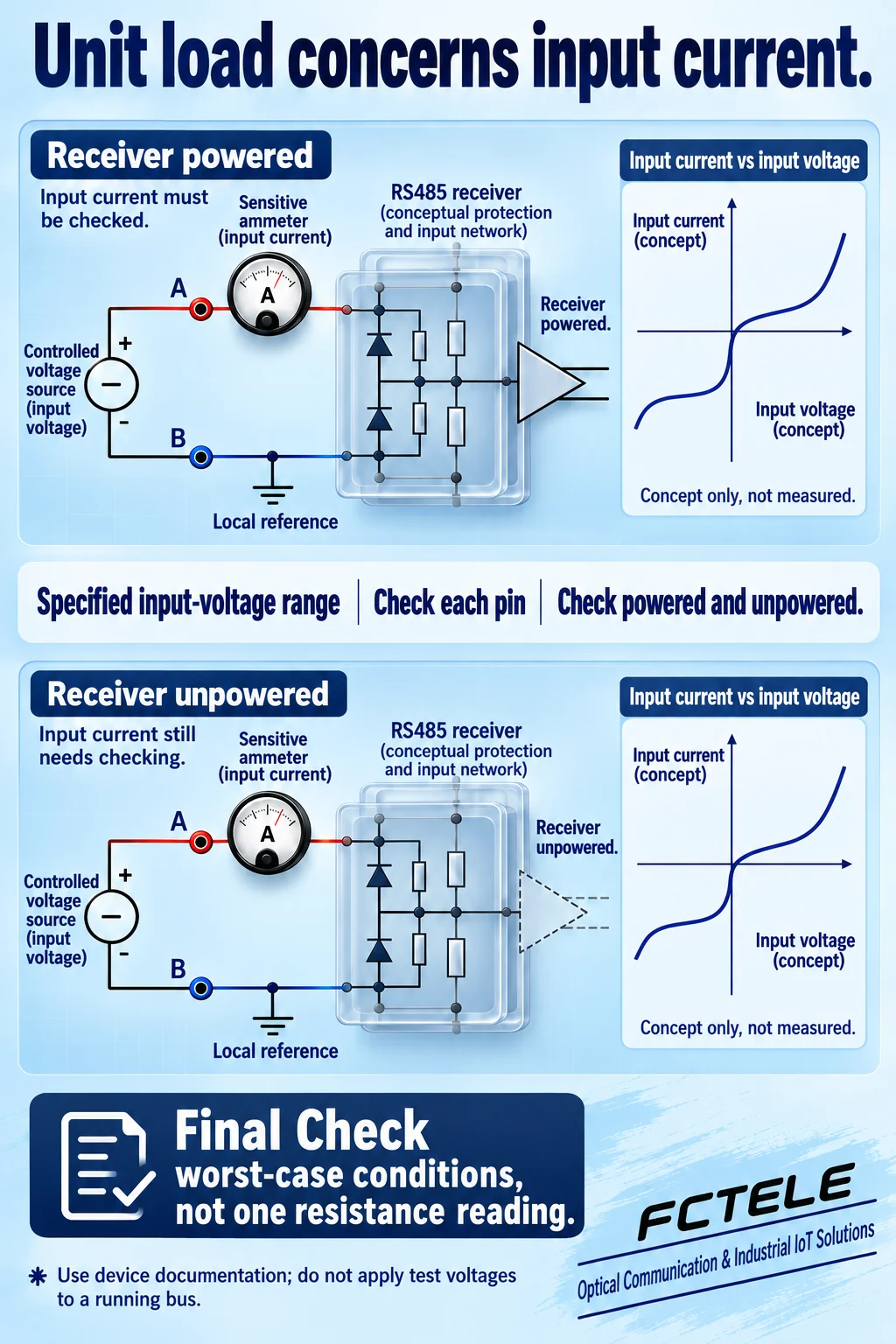
A smaller share does not guarantee more field devices
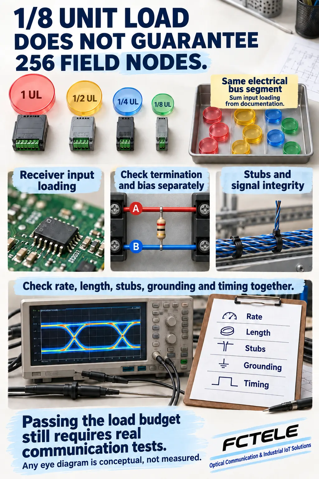
If each receiver input consumes a smaller share, a given input-loading budget can potentially accommodate more inputs. That explains why some low-load component references give theoretical connection counts above 32. They describe possibilities under particular loading conditions rather than a field limit that applies unchanged to all equipment and wiring.
For example, one-eighth-unit-load receivers are often discussed with a theoretical 256-node example. That number must retain its driver, additional-circuit and specified-condition assumptions. An example for one transceiver IC is not a capacity guarantee for every serial device server. Finished equipment also includes protection, bias and the actual interface implementation; check the equipment documentation.
When mixing devices, do not assume every enclosure presents the same share. Record the evidence for each connected receiver input, total the burden for the same electrical segment, and identify missing information. If a node contains more than one input actually connected to the bus, interpret the real connection rather than counting only software station addresses.
Termination, bias and stubs cannot all be covered by one UL number
The bus may also contain termination, external fail-safe bias and other interface circuits. A termination resistor is normally connected across the two conductors and primarily deals with reflections at transmission-line ends. It loads the driver, but it is not another receiver device. Do not add a termination casually at every device.
Bias can help an idle bus satisfy its design requirements and can also consume current budget. It is related to receiver loading, but saying the UL calculation is done does not remove the need to examine it. For built-in circuitry, check where and when it is enabled rather than inferring settings from the enclosure, terminal colors or another product.
Other problems arise during signal transitions. Cable propagation, stubs, input capacitance and signal edges affect the waveform. Even when the steady-state budget is within limits, a long stub or unsuitable topology may cause a receiver to decide incorrectly at a critical instant. Loading and signal integrity are related but distinct checks.
Draw the electrical segments in a serial-server project
Feichang’s FCT-1100-F1S1 compact single-port three-in-one serial device server provides a real product context for RS232, RS422 and RS485 interfaces. It illustrates why the network and serial sides need separate consideration. This article does not infer its transceiver IC, UL rating, internal bias or maximum supported node count.
Delivering bytes over the network to a serial server does not automatically solve driving the RS485 side. Establish which devices share the same pair and where an active repeater or other converter actually re-drives a signal. Whether a new electrical segment exists depends on the documented function, not merely the presence of another box.
Optical transport, network connectivity and RS485 electrical loading have different budgets. Network session capacity, serial-channel count or fiber distance cannot substitute for receiver-input capacity on one RS485 segment. Relate each physical connection and port role to the exact product evidence so that parameters from different layers are not mixed.
Turn a node-count claim into a record with conditions
Preserve the device list, evidence for each interface’s loading, power states, and termination and bias locations. Record the data rate, cable length, stubs and communication timing as well. Distinguish conditions permitted by documentation from conditions actually present. A hypothetical example must not be represented as completed measurements or a manufacturer commitment.
Then verify actual communication in an authorized environment, including the far end, device changes and power-off cases that the design needs to cover. Investigate errors using waveforms, interface states and protocol records. Do not attribute every missing byte to too many nodes, or treat a few devices working temporarily as proof of maximum capacity.
Beginners can remember three points: receiver inputs are not zero burden; unit loads are not enclosure counts; and passing a budget still requires real communication checks. For a firm capacity requirement, obtain a formal statement for the exact model, wiring and operating conditions instead of remembering one number stripped of its assumptions.
Primary references
TI RS-485 Basics: Unit Loads and Node Count; TI: The RS-485 unit load and maximum number of bus connections; TI RS-485 Basics Series. Product context: Feichang FCT-1100-F1S1 three-in-one serial device server (Chinese). Original illustrations, created with AI assistance, explain generic mechanisms; they are not a particular product circuit, measurements or photographs of a real project.
Translated from the Chinese technical article: Read the original Chinese article.
Common practical questions
Does RS485 allow only 32 devices?
The commonly quoted 32 concerns a unit-loading budget under standard conditions, not a universal enclosure count. Verify receiver UL ratings, driver capability, additional loading, wiring and communication conditions.
Does one-eighth unit load guarantee 256 nodes?
No. It describes a smaller receiver-input share. The theoretical example still has driver and other assumptions. Check the finished interface, termination and bias, cable and stubs, rate and protocol implementation separately.
Can one multimeter resistance reading determine unit loading?
Not by itself. Unit loading concerns input current across a specified voltage range and worst-case conditions, including relevant pins and power states. Start with formal component and equipment documentation; do not apply test voltages to a running bus.
Scope and further reading
Generic RS485 receiver loading and driver-budget concepts; not a particular product circuit, measured capacity or a guarantee of 256 field nodes.
RS485 termination, bias and reliability · UART, differential signaling and half-duplex
