


RS485 reliability design must take care of both the electrical waveform and the communication order. A device that tests fine on a short cable may still fail after it is connected to a long cable, multiple instruments or distributed power supplies, and the cause is often termination, biasing, power-up state or control timing. During design, first draw the network segments and fault boundaries clearly, then establish acceptance conditions that can be retested; this is more useful than applying a fixed distance, a fixed node count or a uniform delay. This article is aimed at design and engineering commissioning, and does not attribute every on-site fault to chip performance.
1. Break reliability down into verifiable conditions
For one query to succeed, the driver must output a differential signal clear enough that the receiver can still decide after the signal has propagated through the cable, the UART parameters must match, the protocol must allow the target device to respond, and the response must return in time. One layer being normal cannot replace the other layers: activity on an oscilloscope does not mean the address is correct, receiving bytes does not mean the checksum passes, and a lit power light does not mean the supply is stable when the load changes. Design targets should correspond to observable phenomena.
First list the nodes, cable length, cable, baud rate, power supply areas and service cycle, and confirm which lines belong to the same electrical network segment. Do not derive the usable node count from a generic theoretical maximum alone, and the distance cannot be decided only by the experience of “how far 485 can go.” The receiving load, bias network, termination and actual edges all change the margin. Only by writing the worst conditions clearly can you know which situations the subsequent tests must cover.
2. Termination matching must follow the network segment
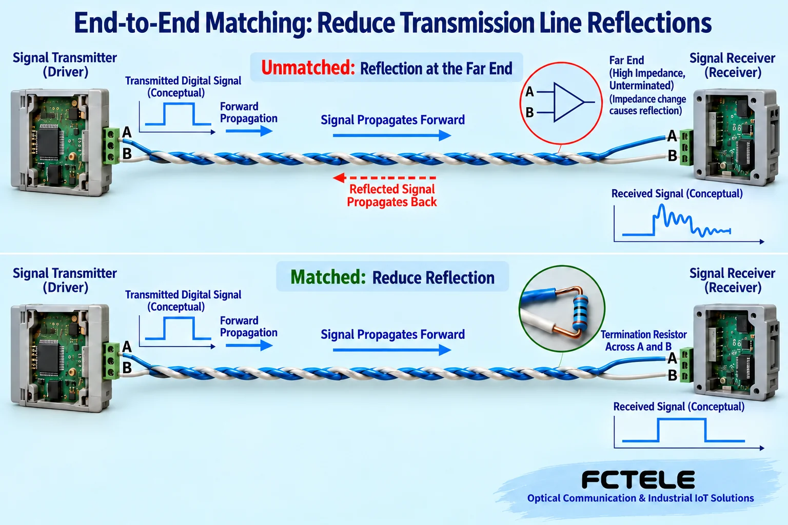
Signal edges propagate along the line, and reflections occur when the impedance at the end does not match. The goal of the termination resistor is to reduce reflections, not to raise the signal voltage. For a common bus, check matching from the two actual ends of the network segment, taking into account the cable characteristic impedance and the device’s built-in termination configuration; intermediate nodes should not enable termination unconditionally. After changing the cable, adding branches or changing the rate, recheck the waveform and load; do not mechanically copy the original short-cable configuration.
RC and other matching methods each have their own design premises, and they cannot replace ordinary termination just because static power consumption is lower. Reflections caused by stubs are also affected by length and edges, and there is no universal number of meters that guarantees all rates are safe. When crossing multiple wiring directions, evaluate an active HUB with independent driving so that each branch becomes a network segment that can be designed separately; directly twisting several groups of wires together will not provide this electrical boundary.
3. Biasing and fail-safe must be calculated for the whole network
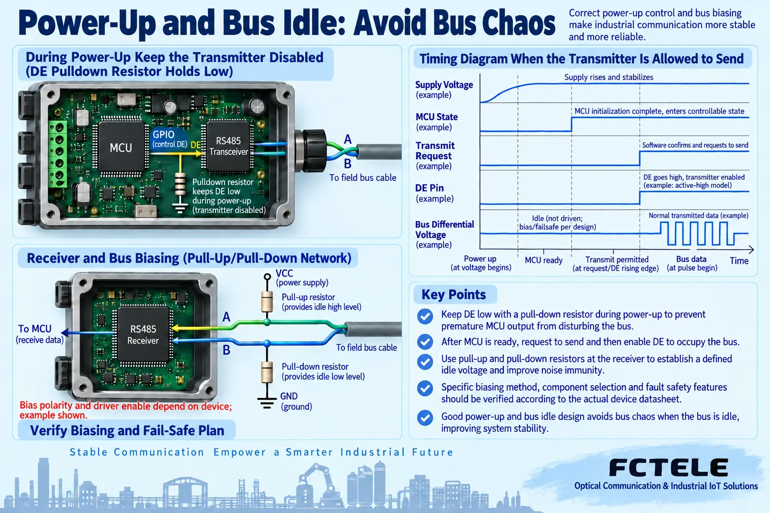
When idle, no driver is actively transmitting, but the receiver still needs a definite state. Some devices have open-circuit, short-circuit or idle fail-safe functions, while traditional receivers may need external biasing. The bias resistors must be calculated together with the termination, power supply, receiver load and threshold. Adding bias repeatedly at every node may increase the load or change the potential, so a fixed resistance value cannot be copied for all systems.
It is also necessary to distinguish bus biasing from a pull-up on the receiver logic output. Adding a resistor to the UART receive pin does not mean that an idle differential state on the line has already been established. Fault testing must also distinguish open circuit, short circuit and no driver, because these states are not necessarily handled the same way on different devices. Selection and testing should be based on the datasheet definitions, not just on the words “with fail-safe.”
4. Power-up and reset must not let the driver seize the bus
When the controller powers up, the program has not yet initialized, and the GPIO may not yet be in the expected state. If the driver enable is mistakenly turned on at this stage, one node may occupy the bus and prevent other devices from responding. The hardware should establish a predictable default state according to the actual chip’s active level, and the software should allow transmission only after the serial port and protocol are ready. The pull-up or pull-down choice for the enable must be checked against the device; there is no single direction that applies to all circuits.
Testing must not be limited to powering everything up at the same time. It should also observe the behavior when one unit restarts alone, when the master restarts, when recovery occurs after a supply drop, and when a node is added while the line already has traffic. Record whether long driving, illegal characters or repeated commands occur. Automatic transceiver devices can simplify direction control, but they cannot replace reset, buffering and error recovery design, and in particular you cannot infer from “automatic” that there is no propagation or switching delay.
5. Isolation and protection cannot replace each other
When crossing power supply areas, the ground potentials on the two sides may differ. Differential reception does not allow unlimited common-mode voltage, and isolation can reduce the risk of DC conduction within the specified boundary; signal isolation also requires an independent supply or corresponding power isolation. Surges, electrostatic discharge and continuous overvoltage are different conditions, and isolation withstand voltage is not the voltage that the port is allowed to input continuously. The protection network must be coordinated according to the transient waveform, energy and transceiver capability.
Feichang Technology FCC-RD documentation provides examples of active isolation and direction control, while FC-D8JM emphasizes an independent isolation structure for the main port and each downstream port. The former is used for interface conversion, and the latter is used for multiple branches; the port capability of one model cannot be applied to another. Check the power supply, isolation domains, protection tests and fault recovery behavior of the specific ordered version; “industrial grade” is only the starting point of the requirement and cannot replace item-by-item verification against project conditions.
6. Make acceptance able to reproduce the worst conditions
First establish a short-cable single-node baseline, then connect the field cable and add loads one by one. Run with the real message length and polling cycle, and record successes, timeouts, checksum errors and the longest response time. The timeout should cover direction release, line propagation, device processing and intermediate device forwarding; you cannot declare all protocols compatible just by adding a fixed delay. Repeated retries occupy the bus and may expand a local problem into the whole network slowing down.
Within the permitted test window, verify power-up, disconnection, node abnormality and recovery separately, and avoid using a live production control line as a test bench. Change only one variable at a time, and save the configuration and waveform before and after. If occasional errors still exist after recovery, continue to look for the corresponding load, temperature or interference conditions; you cannot end acceptance with one successful read. The final document should include the network segment diagram, termination and bias positions, address and parameter tables, instrument conditions and service test results, so that maintenance personnel can repeat the same verification.
Source verification:TI RS485 Design Guide; TI Idle Fail-Safe Note; TI Isolated Transceiver Documentation (General Principle); Feichang Technology FCC-RD Specification; Feichang Technology FC2P-D/Q/R Ring Network Product Documentation. The illustrations are general principle diagrams, not actual product photos, actual PCBs or measured waveforms. Specific parameters and capabilities are subject to the corresponding model, version and delivery documentation.
Translated from the Chinese technical article. Source first published: 2021-12-03. Source last revised: 2026-10-13T12:28:34+08:00. Read the Chinese source
