


UART CHARACTER TIMING
How does UART receive without a shared clock?
A receiver uses a valid start event to establish timing, then samples character bits with its own local clock and checks the stop position. Both endpoints need compatible settings. A new character can realign timing, but framing checks do not prove data integrity or application success. These simplified logic diagrams are not connector voltages or product measurements.
Start
A valid start event establishes the local timing reference.
Sample
Sampling within stable bit intervals helps avoid transitions.
Stop
A low at the expected stop position can flag a framing error.
Record baud rate, data bits, parity and stop bits at both ends.
Compare logic timing and receive errors in an authorized test.
Check actual application bytes and message interpretation.
Selection and verification checklist — expand
| Check | What to confirm | How to verify |
|---|---|---|
| Interface | Electrical compatibility | Read model documentation |
| Character | Timing and format match | Compare both configurations |
| Application | Bytes and messages correct | Retain known-pattern test records |
Serial endpoints do not share a separate clock wire, so how does a receiver identify a byte within a changing signal? Start bits, stop bits and each endpoint’s own timing provide the answer. Understanding that process explains why a small configuration difference can produce corrupted characters or framing errors, and why an Ethernet connection does not prove correct serial reception.
Separate the electrical interface from the character format
Industrial equipment may connect to serial device servers or data optical transceivers through RS232 or RS485. An interface transceiver converts line signals into logic signals the chip can process. The UART handles individual bits according to the selected character format. UART means universal asynchronous receiver/transmitter; asynchronous operation normally has no shared synchronizing clock wire.
High and low in these illustrations represent UART logic states, not actual RS232 connector voltages or either RS485 conductor’s voltage to ground. Interface type, reference ground, differential wiring and device limits require separate checks. A logic diagram is not a wiring guide, and TTL pins must not be connected directly to an incompatible interface.
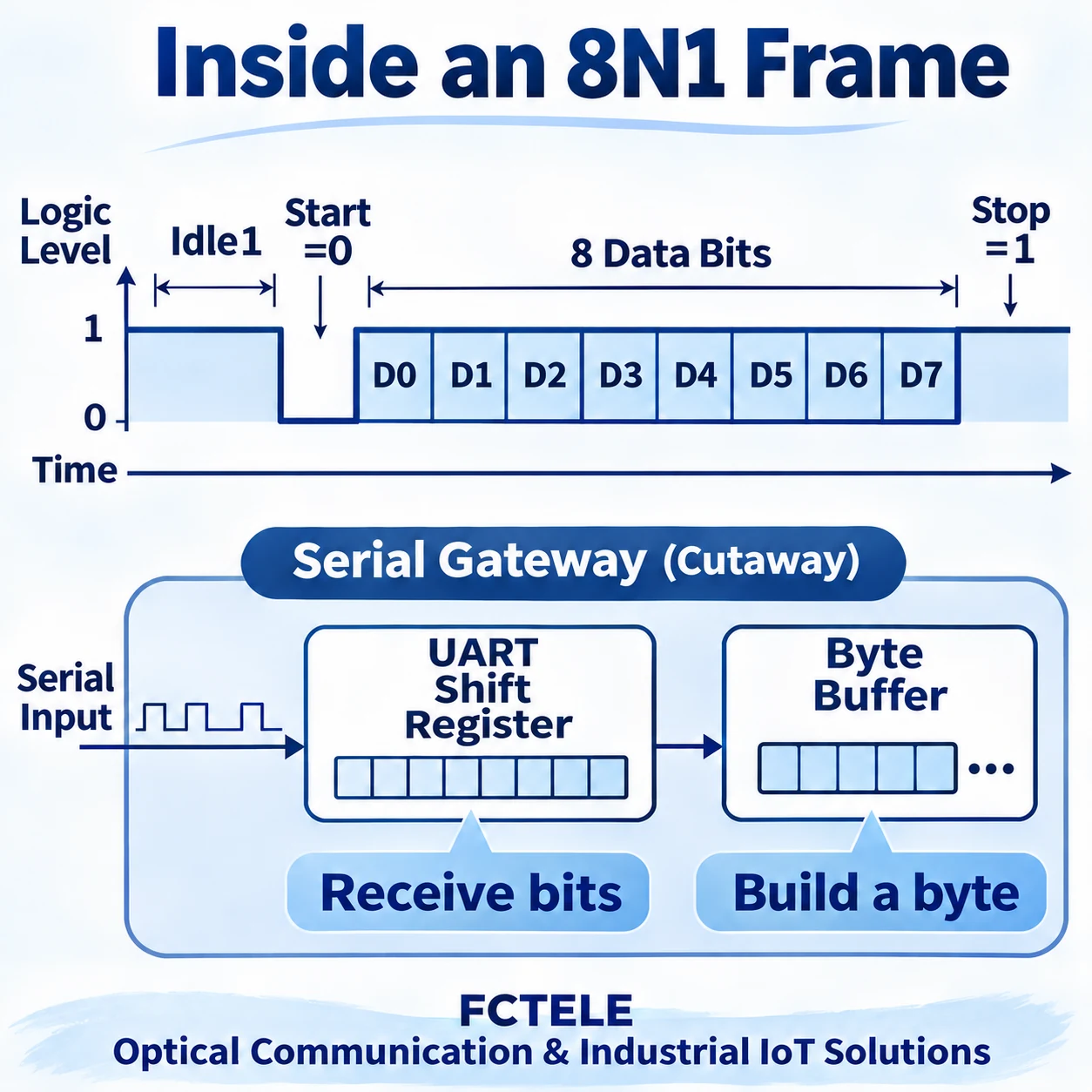
The receive path can be simplified to line transceiver, UART receive logic, byte buffer and application. Passing a signal between stages does not establish that the application received a correct business record. Character reception must work before data enters the network.
Which parts of a frame are not application data?
In the common 8N1 format, 8 specifies eight data bits, N means no parity and 1 specifies one stop bit. A character also contains a start bit, so eight application data bits are not the entire line transmission. Start and stop bits organize characters; they must not be appended to application data as extra values.
In the common non-inverted logic representation, idle is high, the start bit is low and the stop bit returns high. Data is commonly sent least-significant bit first, although peripheral options vary and both endpoints’ documentation must agree. D0 through D7 label positions, not a fixed byte or mandatory transitions between adjacent bits.
Equal consecutive data bits can keep the line at the same state. A receiver cannot count transitions to count eight bits. It relies on timing after the start event to judge successive bit intervals. This is why matching baud-rate settings matters.
How does reception start from idle?
The UART monitors its input. After detecting a possible start transition, it checks the low state against its implementation’s start conditions and schedules data sampling. A short glitch is not automatically a complete start bit. Filtering and start validation vary between peripherals; equipment must not be assumed to use identical internal logic.
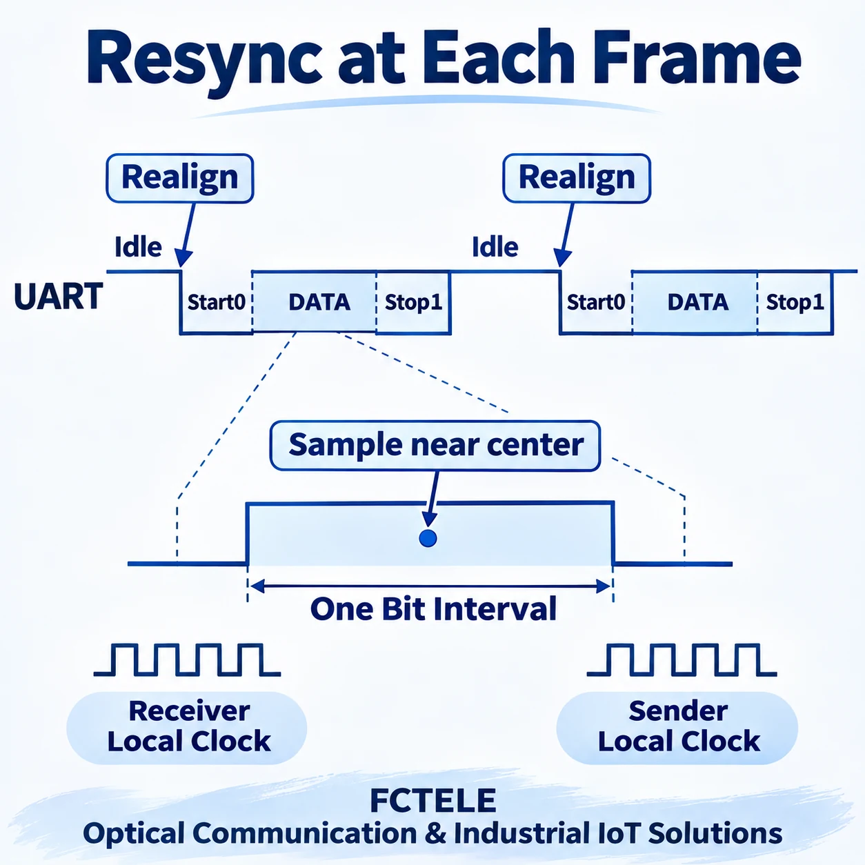
Think of the start bit as a ready-to-begin cue before each character. Both endpoints agree on the approximate pace, then the receiver follows its local timer to sample in sequence. The analogy does not mean a literal spoken cue is sent or that an ordinary UART automatically recognizes any baud rate. Compatible configuration is still required.
Many UARTs use oversampling: their internal sampling clock runs several times during a bit interval, helping establish a valid start or sampling position. Some use multiple-sample decisions. This can help with edge location and disturbances, but does not tolerate unlimited error. One chip’s sampling factor is not a universal FCTELE product specification.
Why sample near the middle of a bit?
Near a bit boundary the signal may be transitioning. Propagation, edge speed and input thresholds influence when the receiver judges it high or low. Sampling within a stable interval makes interpretation easier than sampling next to an edge. The middle dots explain the concept; they do not claim a real chip samples only once or always exactly at the geometric center.
Transmitter and receiver use separate local clocks. If they disagree about bit duration, predicted sampling positions can progressively drift even after the start aligns them. Timing differences can become more evident toward the end of a character, potentially placing a sample in the wrong interval near the final data or stop bit.
Occasionally correct short messages do not prove a reliable configuration. Some bit patterns can mask a problem while others expose it. Acceptance testing should cover real application content and sustained transmission, rather than treating a few readable terminal characters as sufficient evidence.
What can the stop-bit check tell us?
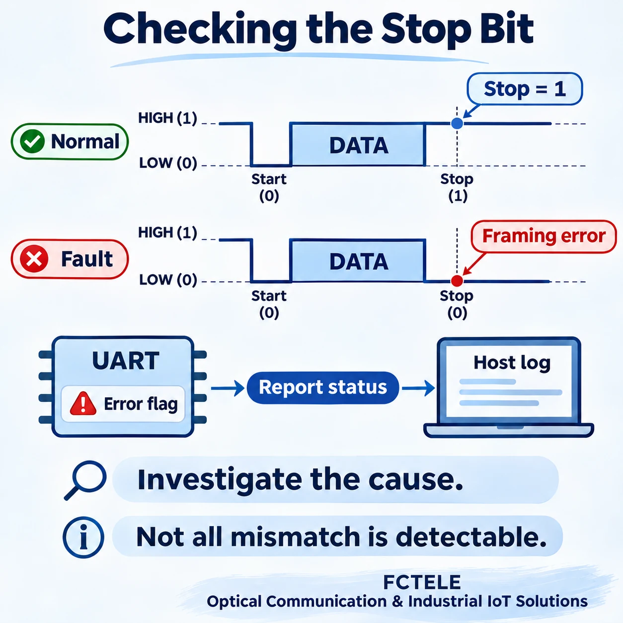
After the configured data and optional parity bits, the receiver checks the stop position according to its implementation. If it sees low where the stop state is expected, it may set a framing-error status. A framing error reports a failed receive-format check; it does not identify which wire is faulty.
Mismatched baud rate or character format, interference and an abnormally sustained low state can produce related symptoms. Conversely, the absence of framing errors does not prove correct data: an incorrect sample can happen to see high at the stop position. Data still needs integrity or application checks. The stop bit is also not an end marker for a complete business message.
How error flags accompany characters, whether a driver discards them and whether software can access counters depend on hardware and software. An application showing nothing does not immediately prove no line input; a stage may have filtered erroneous characters. Preserve status alongside byte contents.
How can the next frame regain timing?
After a character, the receiver returns to looking for another start event according to its rules. A new valid start gives reception an opportunity to realign. Continuous transmission need not contain a long silent gap between characters, but it must meet the configured character format and stop-duration requirements.
Character-by-character synchronization does not automatically correct an entire exchange. If a character is received incorrectly, the application protocol must still handle missing, repeated or corrupted bytes. UART character boundaries, serial server network-packet boundaries and application message boundaries are different. Adding stop bits cannot replace correct message parsing.
For investigation, record baud rate, data bits, parity, stop bits and interface type at both endpoints, then observe waveforms and error counters under authorized conditions. Change one variable at a time and compare known data before and after the change. Parameter changes on critical production links require a maintenance arrangement rather than uncontrolled trial and error.
Connect evidence across the stages
If the input waveform is already abnormal, investigate electrical interfaces, wiring and interference. If the waveform is recognizable but bytes are corrupted, check character format, timing and sampling. If bytes are correct but the application fails, examine buffering, network encapsulation and application interpretation. Evidence at each stage provides a more useful direction than repeatedly replacing Ethernet switches.
FCTELE serial device servers and data-transmission products connect industrial equipment. Actual interfaces and configuration capabilities depend on the relevant model documentation. This guide explains general UART reception, not a particular product’s internal circuit or measured tolerance, and provides no unverified maximum speed. Delivery evidence should include configurations, test conditions, original waveforms and application verification.
References
TI: UART protocol and error overview; Microchip: asynchronous receiver example; FCTELE serial gateway product information. General illustrations, not product circuit or tolerance measurements.
Translated from the Chinese technical article: Read the original Chinese article.
Common questions
Are UART logic states the same as RS232 voltages?
No. A line transceiver converts electrical signals; verify actual interface voltages and wiring separately.
Does no framing error prove correct data?
No. The stop sample can happen to be high even when data is wrong. Integrity and application checks remain necessary.
Does a stop bit end an application message?
No. It is part of a character format; application protocols define message boundaries.
Scope and further reading
Generic UART timing, not a particular device circuit or measured tolerance.
Serial byte escaping and message framing · Ethernet forwarding and maintenance
