


100BASE-TX PAIR ROLES
What does Auto-MDI-X actually change?
A supporting 100BASE-TX port can select how complete cable pairs map to transmit and receive functions. This reduces straight-through versus crossover selection under supported conditions. It does not repair cable damage or replace negotiation and application checks. The two-pair example is not a Gigabit signaling model or a particular chip circuit.
Match
Each transmit path must reach the opposite receiver.
Select
A supporting implementation selects an allowed whole-pair mapping.
Inspect
Role switching cannot repair missing copper or poor contacts.
Record the exact interface, medium and supported functions.
Use a known-good cable and examine link state and counters.
Test installed cabling and the agreed application traffic.
Selection and verification checklist — expand
| Check | What to confirm | How to verify |
|---|---|---|
| Port | Medium and automatic functions | Read endpoint documentation |
| Cable | Continuity and performance | Use suitable cable tests |
| Application | Traffic and stability | Retain agreed test records |
Older instructions may require a crossover cable, while newer equipment works with either suitable cable type. The difference is whether the port can adjust its transmit and receive pair roles automatically. This guide follows a 100BASE-TX copper port through its connector and physical-layer routing, then explains the cable faults that Auto-MDI-X cannot repair.
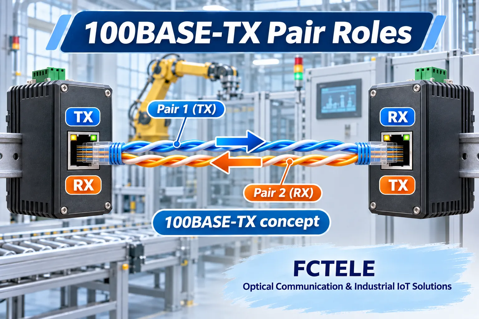
Transmission must reach reception
100BASE-TX uses two signal pairs, each consisting of two conductors working together. One pair carries this endpoint’s transmitted signal and the other carries the peer’s signal into its receiver. Each transmit path must ultimately reach the opposite receive path. Inserting two plugs is not sufficient by itself.
A pair is not any two arbitrarily selected wires. Twist structure, termination and installation quality affect transmission. Paired arrows here represent whole differential pairs, not two independent data channels. Connector pin numbering also depends on viewing orientation; actual wiring requires explicit port and cabling documentation.
This example does not apply unchanged to every speed. 1000BASE-T normally uses four pairs with simultaneous bidirectional signaling on each pair. Its signal processing cannot be reduced to this two-pair, one-direction-per-pair sketch. Identical RJ45 shells do not imply identical internal operation.
What do straight-through and crossover cables change?
Straight-through wiring preserves the defined corresponding pin connections. Traditional 10/100 crossover wiring exchanges the relevant transmit and receive pair positions between ends. That changes connectivity; it does not upgrade cable category or amplify a weak signal.
Older fixed-role ports distinguish MDI from MDI-X: two assignments of transmit and receive functions to pairs. Different endpoint combinations can therefore need different cable mappings. Recommendations based on terminal-to-switch or similar-device connections are shorthand for role matching, not a special electrical property of the device name.
If neither port can adjust and transmit connects to transmit while receive connects to receive, a usable link may not form. This is not yet an IP-address issue. Changing a gateway address usually cannot repair a physical connection that has not become operational.
What happens inside an Auto-MDI-X port?
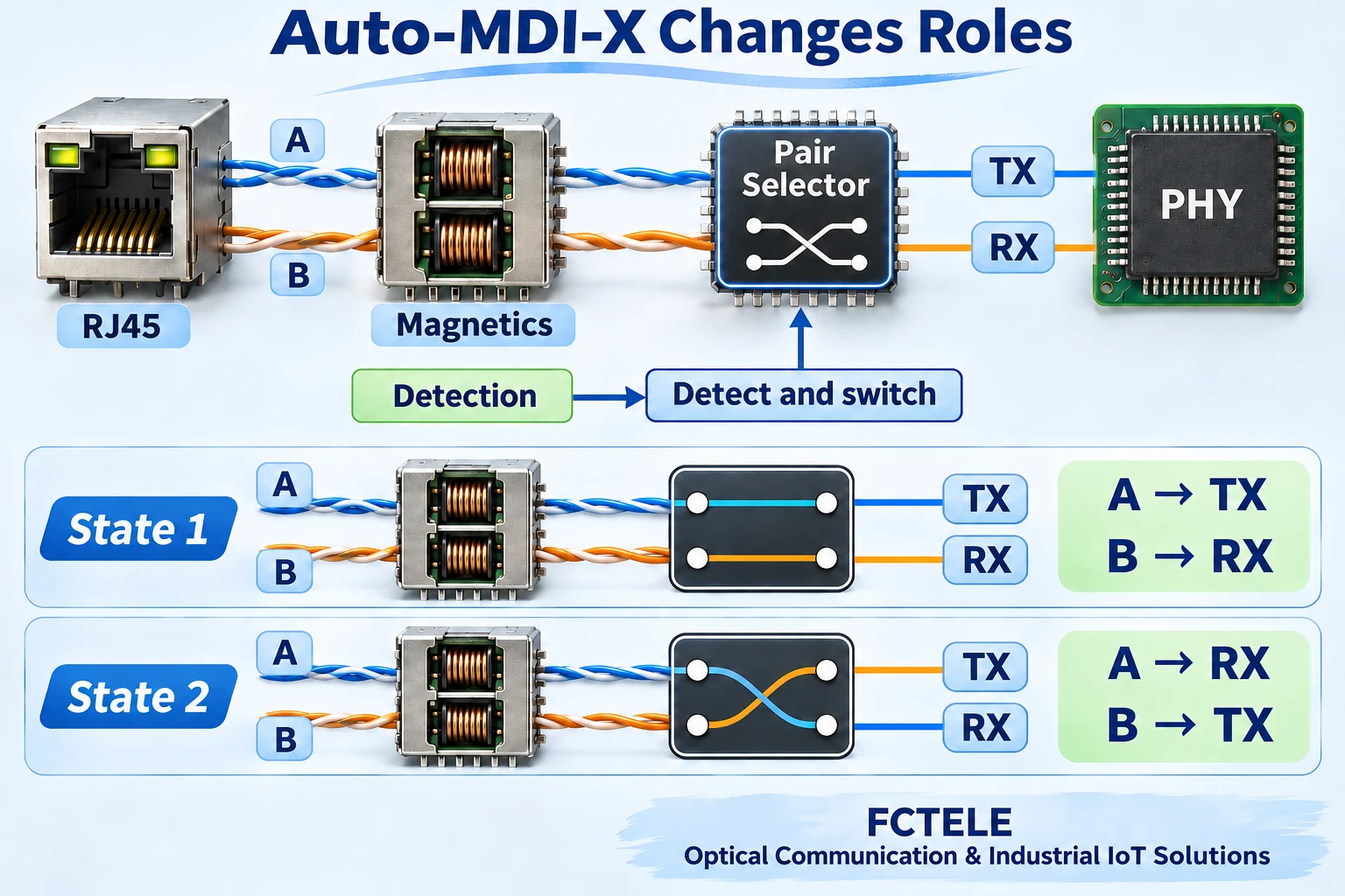
A PHY is the physical-layer transceiver connecting network digital logic to the medium. A supporting PHY or port implementation detects pair connectivity during link establishment and selects an allowed routing arrangement so the cable-side channels match its internal transmit and receive functions.
Think of a two-way patch selector: the external pairs remain intact while their association with internal transmit and receive paths changes. Real implementations can integrate this into analog and digital circuitry rather than using the mechanical switch suggested by a conceptual drawing. The illustration explains path selection only.
Detection, trial switching and link confirmation vary by PHY. This is not recognition of arbitrary wiring. Whether the actual port supports the feature, enables it by default, exposes manual controls or establishes a link within a given time must be checked in model and firmware documentation. The term industrial switch alone establishes none of those details.
Pair switching and auto-negotiation have different jobs
Auto-negotiation exchanges capability information so the endpoints can select a mutually supported operating mode. Auto-MDI-X concerns pair-role mapping. They can cooperate during startup, but solve different problems. Successful speed negotiation does not establish complete cable quality.
Some equipment requires negotiation to be enabled for automatic pair selection. Other PHYs offer particular forced-mode capabilities. Do not assume that forcing 100 Mbps always preserves pair switching, or that every implementation has the same limitation. Check both endpoints before selecting fixed speed or duplex.
Exchanging whole pair roles is also different from reversing polarity within one pair. Some transceivers provide separate polarity detection or correction. These features are not one universal wiring repair function. Interpret reported speed, duplex and pair state as distinct observations.
Automatic matching does not eliminate cable testing
Open conductors, poor contacts, inappropriate pair assembly and inadequate transmission performance cannot be fixed by changing transmit and receive roles. Internal routing cannot replace missing copper or restore damaged twist structure. A link light establishes some startup conditions, not sustained application quality.
A simple continuity check detects some opens or shorts but may not sufficiently characterize crosstalk, attenuation or split pairs. Cable acceptance should match the installation and application requirements. Automatic port functions do not justify omitting suitable tests. Intermittent contacts are especially easy to misjudge when a link occasionally comes up.
Industrial installations also involve temperature, vibration, connector strain and interference paths. Substituting a known-good short patch cable can help isolate a segment, but a successful short connection does not certify the installed run. Record the substitution location and conditions and limit conclusions to what was tested.
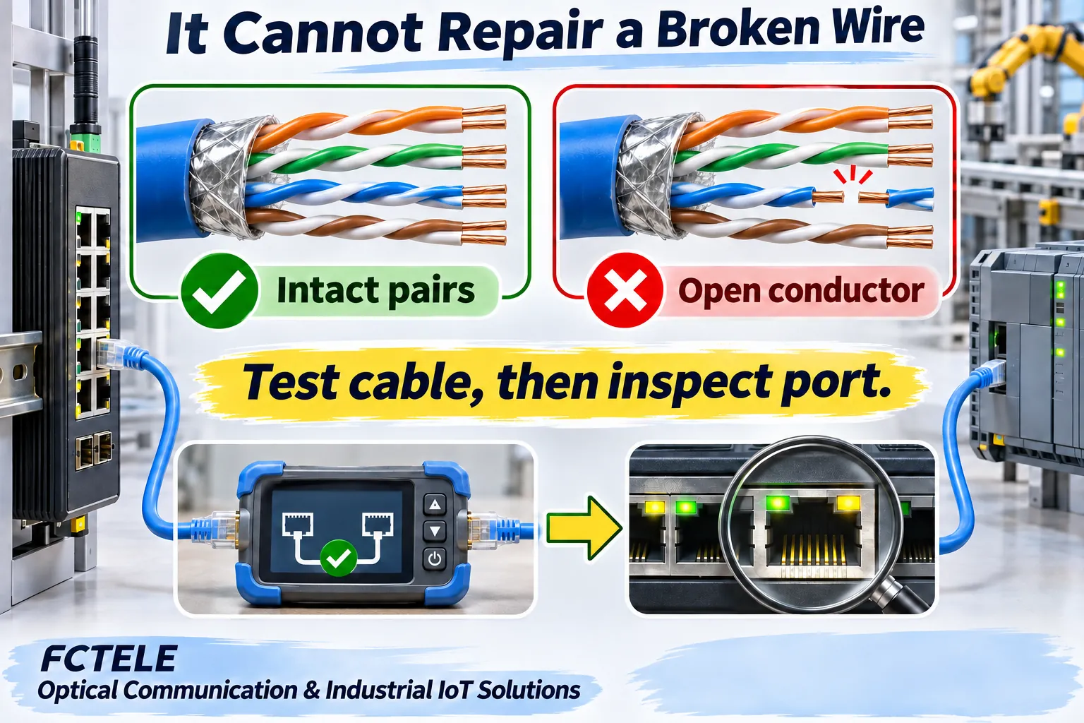
Collect evidence along the signal path
First confirm compatible copper Ethernet interfaces, power and enabled ports, then examine cables and connectors. Use a known-good patch cable between authorized test ports and observe link state, actual speed and duplex. If that works, inspect the original run and intermediate connections segment by segment.
Check documentation and management state next: is Auto-MDI-X supported and enabled, does a forced setting affect it, and do endpoint settings conflict? Change one condition at a time and retain the original configuration. Avoid repeated port resets or forced speed changes without understanding production effects.
After link establishment, run the agreed application traffic and examine errors, discards and stability. If frames are being exchanged but the application still fails, proceed to VLANs, IP configuration and the application itself. Separating pair roles, link operation and upper-layer communication keeps investigation at the appropriate stage.
If receive errors rise mainly in one direction, investigate port counters, the cable and endpoint conditions together rather than immediately blaming pair switching. Retaining counter changes for both directions is more useful than recording only an aggregate error total.
Use specific documentation to establish product capabilities
FCTELE publishes information for managed industrial switches and other equipment. Check the selected model’s copper speeds, medium, configuration options and firmware documentation. This guide does not claim a particular FCTELE PHY design or treat third-party chip specifications as complete product specifications. Fiber SFP connections require their own module, fiber and transmit/receive checks; copper pair switching does not describe their operation.
Auto-MDI-X reduces manual straight-through versus crossover selection under supported conditions. It matches valid cable pairs to transmit and receive functions, but does not repair damage or replace acceptance testing. Retain models, versions, configuration, cable tests and application results so that a successful connection becomes a reviewable delivery result.
References
TI: DP83848K example PHY features; Cisco: Ethernet negotiation and cable connections; Fluke Networks: cable test coverage; FCTELE managed industrial switch information. Third-party chip specifications are not complete FCTELE product specifications.
Translated from the Chinese technical article: Read the original Chinese article.
Common questions
Can Auto-MDI-X repair a broken wire?
No. It matches whole-pair roles, without restoring copper or cable performance.
Is negotiation the same as pair switching?
No. Negotiation exchanges operating capabilities; pair switching matches transmit and receive roles. Enabling conditions vary.
Does the two-pair sketch describe Gigabit signaling?
Not directly. 1000BASE-T normally uses four pairs with bidirectional signaling on each pair.
Scope and further reading
Generic 100BASE-TX concepts, not a particular chip circuit or wiring instruction.
