


One module, two paths to verify
Identify
Read the ID memory with the fiber disconnected.
Check
Compare the low eight bits of the sum with CC_BASE.
Verify
Connect the fiber and check actual traffic separately.
Bench verification checklist
Record the port, module identity and time before connecting the fiber. Then check link state and send an identifiable test frame.
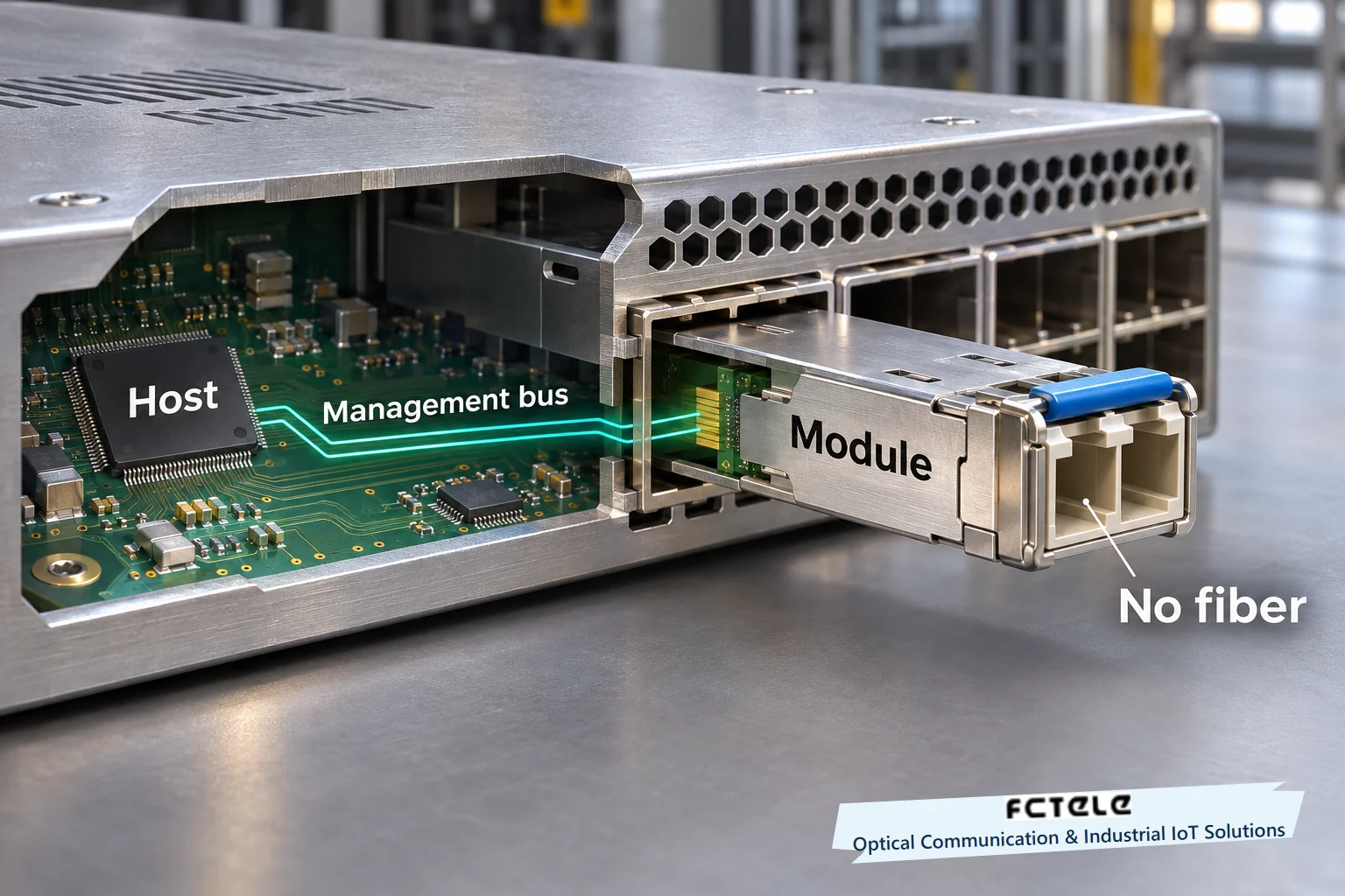
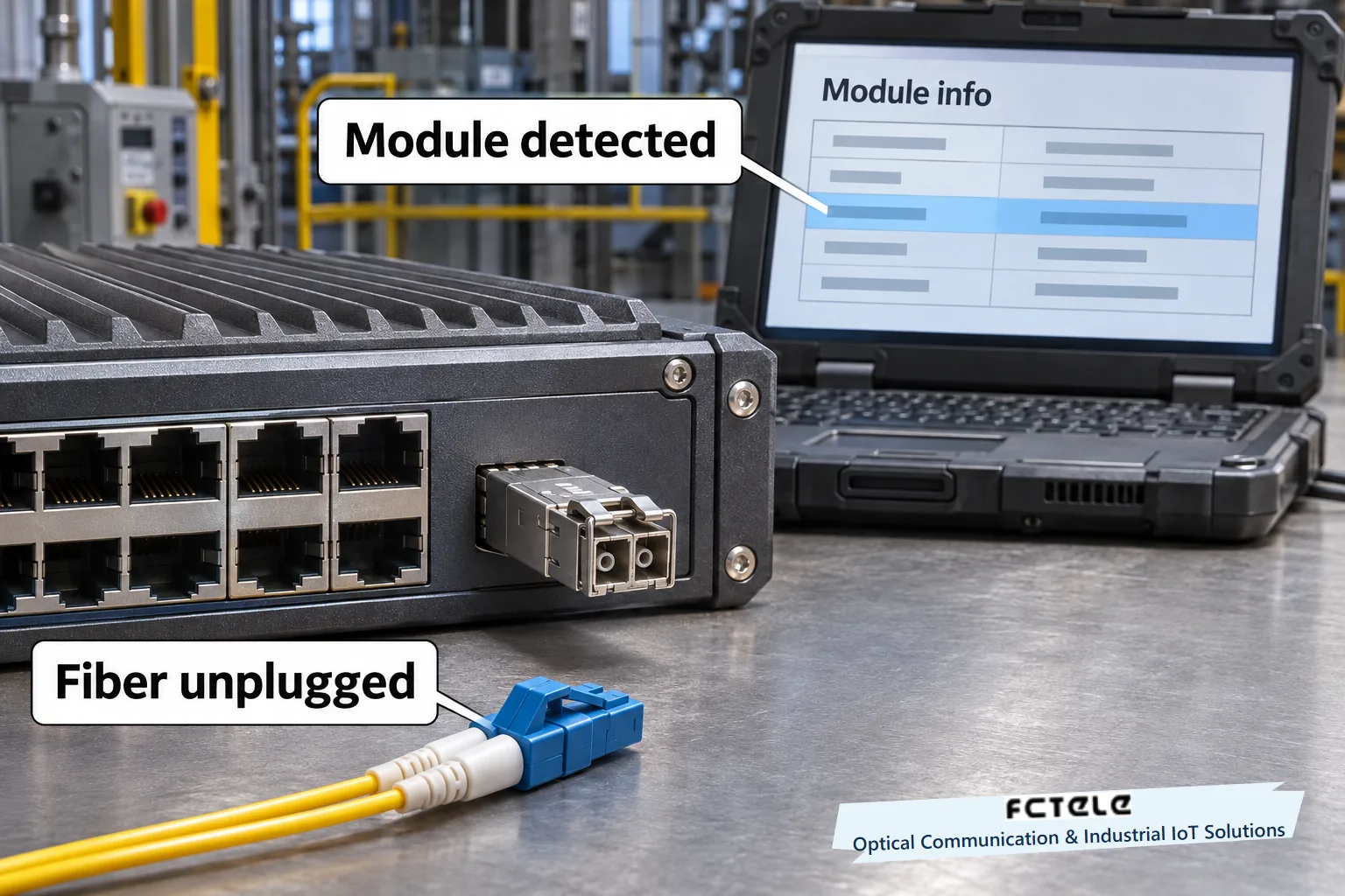
Insert an SFP transceiver into an industrial switch on a test bench, leaving the fiber disconnected. The management page may already show the vendor, part number or serial number while the port still reports link down. Those details come through the electrical interface at the rear of the module. The switch reads the module’s reported identity over a low-speed management channel. Traffic uses a separate electrical and optical path. Each path provides a different kind of evidence.
Two paths through one module
The module slides into the front-panel cage and its edge contacts mate with the host connector. Power and ground bring up the module electronics. On equipment with the traditional SFP management interface, a presence signal can tell the host that a module is in the slot. The host can then use a low-speed two-wire interface to retrieve its information. Presence alone tells the host that something is installed. Displaying a vendor or part number requires successful communication and interpretation of the bytes. Initialization delays, error messages and retry behavior depend on the host implementation.
The two wires are SCL, the clock, and SDA, the data line. Think of the switch asking the module for bytes at a given offset and interpreting the result according to an agreed layout. This takes place inside the chassis. The optical connector can be empty and the far end can be powered off. In the separate high-speed path, the host exchanges traffic signals with the module over a high-speed electrical interface. The transmitter converts electrical signals into light and the receiver converts light back into electrical signals. The fiber, far-end device, receiving conditions and link mode matter to this second path.
The specification for Feichang’s DIN-rail Layer 3 switch with four 10-gigabit optical ports and eight gigabit copper ports lists SFP module information as a management feature. It provides a real setting for the explanation. The diagrams illustrate generic functions. The product document does not describe the board routing, polling sequence or transceiver acceptance policy for that model. Use a transceiver and port mode supported by the applicable device documentation.
Which bytes identify the module?
Traditional SFP modules and optical transceivers that use the SFF-8472 management map store identity information at defined byte positions. The specification labels the base address A0h. A tool using seven-bit I²C notation calls that address 0x50. The two forms differ because the address byte includes a read/write bit. Shift 0x50 left one position and the write address byte is 0xA0, while the read address byte is 0xA1. These are different representations of the same device address. Entering 0xA0 into a tool expecting seven bits can make a working module appear unresponsive.
The device address and the field offset serve different purposes. The former selects the identification area and the latter locates a byte within it. In this map, byte 0 identifies the device type and byte 2 identifies the connector type. Bytes 20 through 35 hold the vendor name, bytes 40 through 55 hold the vendor part number, and bytes 68 through 83 hold the serial number. The offsets here are decimal. If the module supports diagnostics, A2h, corresponding to address 0x51 in seven-bit notation, can provide diagnostic data. Reading the base identity establishes neither the availability nor the display of every diagnostic measurement.
For example, the host can interpret the sixteen vendor part-number bytes as text. Suppose four of those bytes are hexadecimal 44, 45, 4D and 4F. They appear as DEMO. Spaces may fill the rest of the fixed-length field. If the management page lacks a part number, check whether the host failed to read the field, found a blank field, or read a value the interface chose not to display. An optical power meter answers a different question. The text on the page comes from an electrical read inside the chassis.
What does the checksum verify?
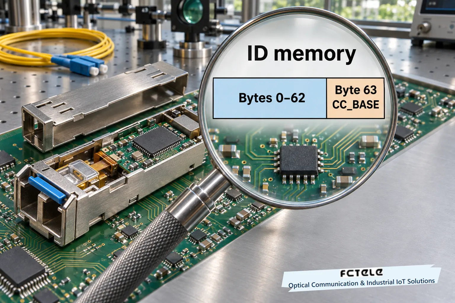
The host can add the contents of the first 63 bytes in A0h, at offsets 0 through 62, keep the low eight bits, and compare them with CC_BASE at offset 63. Suppose the sum is hexadecimal 0x034A. The low eight bits are 0x4A. If byte 63 also contains 0x4A, the check passes. If it contains 0x4B, preserve the raw bytes and check the byte range, revision and whether the same result appears on another read. The numbers illustrate the calculation and were not measured on any Feichang device or transceiver.
A matching checksum shows that these bytes agree with their stored check code. Different byte combinations can produce the same sum. The check does not authenticate the vendor, prove that the fields are accurate, or establish that the host will accept the module. The serial number starts at byte 68, outside the range covered by CC_BASE. The extended identification area has its own check code, CC_EXT. A report stating that CC_BASE passed should name the range it tested.
Identify the stage that produced each reading
If the vendor and part number appear but the serial number is blank, first check whether the interface exposes the serial number. Then consult any raw readout the device supports. Reading bytes 0 through 63 and passing the base checksum establishes that enough data is available from the base area. The serial number starts at offset 68. If the extended area was not read in full, the base checksum cannot turn a blank serial number into a verified vendor value. Recording “base area readable; extended area unverified” is more informative than reporting only that the module was identified.
Consider the opposite case. The network management system retains the previous part number while the switch currently reports that no module is present. Those records describe different moments. Align the polling times and query the current slot again. Otherwise a cached result could be mistaken for a live response and troubleshooting could turn unnecessarily to the remote fiber. Include the port, time and data source so that the local interface, management cache and current bus reading can be distinguished.
Verify management and traffic separately
Use a module confirmed to work with the host. On an isolated test bench, record the port, host software version and module part number. Insert the module with the fiber disconnected, then check whether the host reports presence and shows complete module information. If the part number appears, the management read has supplied at least that field. The traffic link can remain down at this stage. Connect the correct fiber and far-end device according to the documentation. Record the link state and transmit and receive counters at both ends, then send an identifiable test frame to confirm that traffic passes. Keep both results.
If the management interface reports an empty slot, verify the selected port, module seating and documented compatibility. If it reports presence but cannot read the information, try a known readable compatible module in the same port, or move the original module to a known compatible port on the bench. Keep other conditions consistent and record whether the problem follows the module or stays with the slot. If the part number is visible while the traffic link remains down, check the two port modes, fiber transmit-to-receive connections and optical power. Use counters to establish whether any frames pass. Do not look into optical ports or repeatedly reseat modules on a live production link to test identification.
Some hosts cache previously read information, and some expose particular fields only through a designated screen or maintenance interface. Record the read time, port and insertion or removal event, and use the supported refresh or query method. A clear handover record has three columns: module presence, identity read and traffic verification. A screenshot can then be interpreted in terms of what it actually shows.
Sources and scope
SNIA SFF-8472 Rev. 12.5a · Feichang DIN-rail Layer 3 switch specifications (Chinese)
Translated from the Chinese technical article: Read the original Chinese article.
Common questions
Why can the host show a part number without fiber?
The host reads it over the two-wire electrical interface. Fiber carries traffic on a separate path.
Do A0h and 0x50 refer to different devices?
They are eight-bit address-byte and seven-bit address forms for the same target.
Does passing CC_BASE prove the module is compatible?
It shows that bytes 0 through 62 match the check byte at offset 63. Verify compatibility and traffic separately.
Further reading
What a gigabit fiber port sends between frames · Optical power and signal clarity
