


How the PHY hears the far end
Share
Both directions share one pair.
Estimate
The PHY uses its own transmit symbols as the reference.
Subtract
The remainder is 0.22 in this illustrative sample.
Bench verification checklist
Compare a known-good patch lead with the installed channel. Record rate, duplex and counter changes.
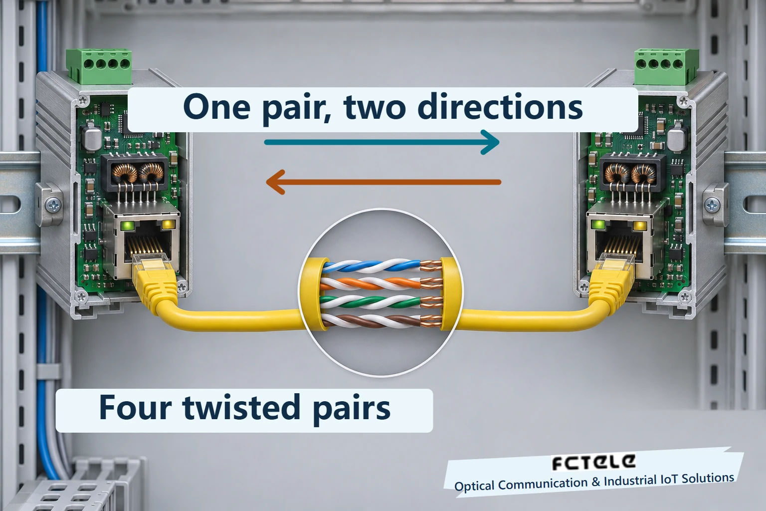
Connect two gigabit devices in a control cabinet and the controller can send a polling request while receiving data from another transaction. A typical Ethernet cable contains eight copper conductors twisted into four pairs. In full-duplex 1000BASE-T, each pair carries both directions at the same time. The receiver can separate them because it already knows its own transmit sequence. It estimates how that sequence reappears in the receive path and subtracts the estimate.
All four pairs work together
Separate the shape of the connector from the transmission rules. A typical 100BASE-TX connection uses two pairs, one for transmit and one for receive. Full-duplex 1000BASE-T uses all four pairs together. Both ends drive each pair, so the pins cannot be assigned a permanent receive-only role. Full duplex means the directions can run concurrently. It does not double the link rate in either direction.
The switch logic in the cabinet processes Ethernet frames. The physical-layer transceiver, or PHY, encodes digital information into electrical signals suited to twisted pair and couples them to the cable through the port magnetics. The far end does the same. The illustration highlights one pair so the directions are easier to follow. A gigabit transceiver processes and aligns the symbols received across all four pairs to reconstruct the data. Losing a pair does not simply remove a fixed fraction of gigabit capacity.
The applications see a bidirectional link while the circuit sees two differential signals superimposed on one pair. A differential receiver responds to the voltage difference between the conductors. This rejects some interference picked up similarly on both wires. The local transmitter also produces a differential signal, though, so taking the difference between the wires does not tell the PHY which end sent it.
The analog front end reduces the local signal first
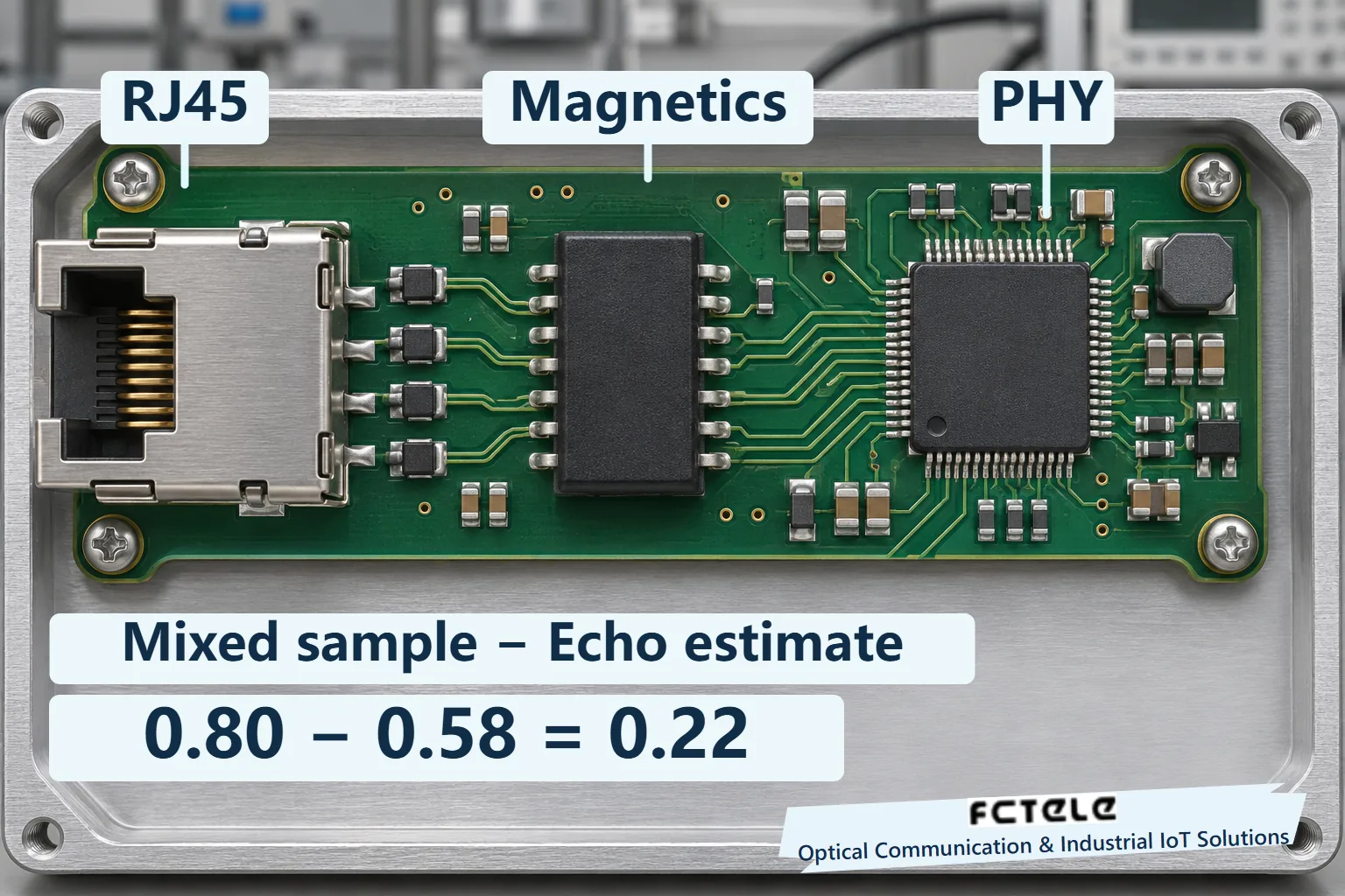
Consider a generic port board. The connector and magnetics sit on the cable side. The transmit and receive circuitry sits inside the PHY. The far-end signal arrives through the cable and magnetics, and the local transmission leaves through the same coupling path. If the mixed waveform were passed straight to the sampler, a strong local component could obscure much smaller changes from the far end after a long cable run.
A common design uses an analog hybrid. It lets transmit and receive share the line-side connection while suppressing some of the local transmit component before sampling. The sampler is then better able to resolve the incoming signal. The connector, magnetics and PHY in the illustration are generic functional locations. The drawing does not identify the chip used in any Feichang product or imply that the hybrid is a separate component visible on the board.
Connectors, patch panels and cable sections cannot maintain ideal impedance at every point. A change in impedance can send part of the local signal back. That reflection takes time to return. Subtracting only the current local transmit signal would still leave delayed components, and different discontinuities can return echoes with different amplitudes and delays. The receiver therefore needs a second stage of cancellation.
Estimate the echo from the known transmit sequence and subtract it
The PHY already has a copy of the symbols it transmitted. Digital receive processing can use the current and earlier local symbols as a reference, weighting the contributions at different delays to estimate the echo at the sampling point. Subtracting that estimate from the mixed sample makes the far-end symbols easier to detect. A change in cabling can change the echo path, so the estimate must track the path rather than applying one fixed amount to every cable.
Take a single hypothetical sample. After the analog front end, the receiver sees a mixed value of 0.8 arbitrary units. Suppose 0.6 is local echo and 0.2 comes from the far end. If the digital processing estimates an echo of 0.58, subtraction leaves 0.22. That is close to the far-end value of 0.2, with a residual error of 0.02. The numbers make the arithmetic checkable. They are neither standard voltages nor equipment measurements. An echo at another sampling instant may be negative, in which case subtracting it increases the result.
Real receivers also encounter crosstalk from other pairs, channel loss and interference between symbols. Near-end crosstalk cancellation and equalization address different effects. These operations occur as the PHY recovers the symbols. The switch logic downstream sees recovered frames or receive errors. A capture from a mirrored switch port can show how frames move at the next layer, but cannot expose the internal echo residual.
Why a short patch lead can work when the installed channel does not
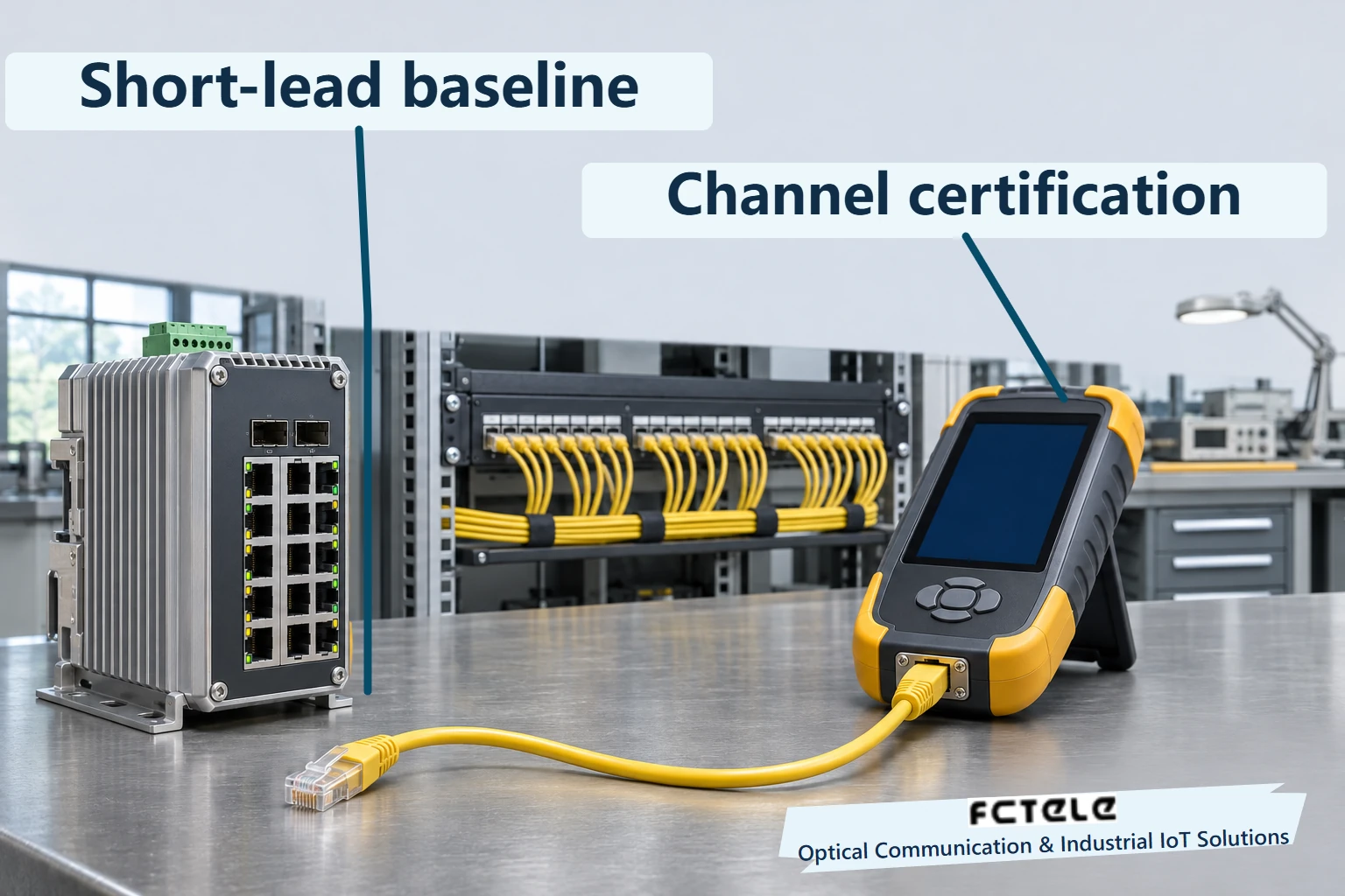
Two devices may negotiate a stable gigabit link over a short patch lead, then renegotiate occasionally or accumulate receive errors when reconnected through the cabinet patch panel and permanent cabling. The comparison narrows the search. A split pair, poor contact, excessive untwist, insertion loss, crosstalk or a configuration difference can all produce similar symptoms. A lit link indicator shows that a link was established at that moment. It does not measure its operating margin.
In an approved maintenance window, record the negotiated rate and receive error counts at both ends. Compare a known-good short patch lead using the same devices, settings and traffic. Restore the installed channel and use an appropriate cable certifier to test wire map, insertion loss, return loss and near-end crosstalk against the limits for the installation. Return loss tells you about reflections in the channel. Receive errors describe how the link performs in service. The results can corroborate each other, but neither reveals the state of the PHY’s internal filter on its own.
If the installed channel shows a problem, isolate the cabinet patch lead, patch-panel termination, permanent cable and field termination, changing one item at a time. Record traffic in both directions and the increase in error counters after each change. Compare observation windows of the same length. Where the project requires longer stability checks, include representative equipment operation, vibration and installed cable restraint. A single bench pass does not establish the reliability of the production path.
Reading product specifications and test results
Feichang’s managed DIN-rail switch with four 10G optical ports and eight gigabit copper ports lists eight auto-negotiating 10/100/1000BASE-T RJ45 interfaces. It is an example of the industrial copper interface discussed here. The particular analog architecture, digital estimation, diagnostics and recovery behavior depend on the equipment. Where a switch also has fiber ports, test the copper channel and the optical power budget separately.
For acceptance, ask three checkable questions. Have the devices negotiated the intended rate and duplex mode? Do reflection and crosstalk measurements meet the selected cabling limits? Can the real application exchange traffic in both directions over time? Device status answers the first question, the cable certifier answers the second, and counters and application results answer the third. This links the reason the PHY can hear the far end to the evidence an engineer can actually collect.
Sources and scope
Marvell 88E1111 PHY §2.6.3 · Feichang four-10G-optical, eight-gigabit-copper industrial switch (Chinese)
Translated from the Chinese technical article: Read the original Chinese article.
Common questions
Does full-duplex gigabit Ethernet dedicate separate pairs to transmit and receive?
Each of the four pairs carries both directions in full-duplex 1000BASE-T.
Does differential reception remove the local transmission?
Differential reception rejects some common-mode interference. The local transmission is itself differential and needs echo cancellation.
Can a packet capture reveal the echo residual?
A normal capture contains recovered frames. Compare channel certification, port counters and controlled substitution tests.
Further reading
Why Classical CAN inserts stuff bits · What a gigabit fiber port sends between frames
