


RS485 / OUTPUT PROTECTION
Why can a persistent fault seem to recover?
An abnormal load can trigger current limiting while the output stage still dissipates heat. Some transceivers shut down when hot and re-enable after cooling. A persistent fault can repeat the sequence. This mechanism is not a universal diagnosis: supply restart and application timers can also produce cycles. Component protection does not establish valid end-to-end communication.
01 · Constrain current
Current limiting constrains an abnormal output load; it does not guarantee usable differential voltage.
02 · Track heating
A device can continue dissipating heat under a limited fault current. Temperature depends on generation and removal.
03 · Verify recovery
Some devices disable and recover thermally. Re-enabled drive is not proof of a valid application transaction.
Identify the device
Use exact equipment and component documentation, not universal limits.
Separate observations
Record supply, line state and application results independently.
Retain uncertainty
State when internal junction temperature was not measured.
Selection and verification checklist — expand
| Check | Confirm | Evidence |
|---|---|---|
| Protection | Exact behavior and limits | Applicable documentation |
| Conditions | Permitted observation points | Authorized bench records |
| Recovery | Complete valid transactions | Matching send and receive logs |
A serial link that works briefly after restarting has not necessarily been repaired by software. Some RS485 transceivers limit output current under an abnormal load. If internal heating continues, they may disable the driver and re-enable it after cooling. A persistent fault can repeat this sequence. The mechanism is a hypothesis to verify, not a diagnosis for every intermittent link.
A short changes the output-current path
An RS485 driver creates a differential signal between two bus terminals. Under normal loading, it supplies current to the line and its termination. A low-resistance connection between A and B can collapse the intended differential voltage while increasing current demand. This changes an electrical path, not an address or parity setting; reconfiguring serial parameters cannot repair that physical connection.
Bus contention is another abnormal condition: multiple drivers try to impose opposing states simultaneously. This differs from a metallic A–B short, but can also stress output devices. Driver-enable timing, node state and wiring matter. One timeout alone cannot distinguish the cause.
The illustrations use a generic output stage and controlled teaching model. Actual protection structures, limits and recovery behavior vary, and equipment can add fuses, isolation, supply protection or channel controls. The fault-path image is not a request to short a live network or a representation of any specific FCTELE circuit.
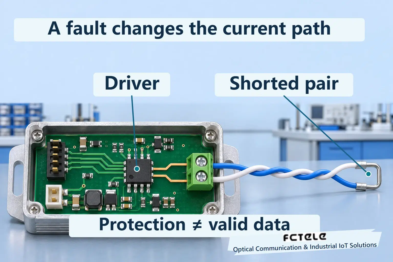
Limiting current does not restore a normal load
Without appropriate protection, a very low load can demand excessive current and electrical stress. A current-limited driver constrains its output, but the limited current may not establish a usable differential voltage. The device might remain intact and attempt to drive while communication is already invalid. Protecting a component and transmitting correct data are different outcomes.
Current limiting also does not eliminate internal dissipation. Current flowing through an output device with a voltage across it can produce heat. Significant heating can remain under some fault conditions. Short-circuit protection therefore does not imply indefinite tolerance of arbitrary voltages, ambient temperatures or external energy. The applicable documentation defines the permitted fault range.
The limiting characteristic is not a universal horizontal line. Direction, fault voltage, supply and temperature can affect it, and some implementations further reduce current to constrain dissipation. This article gives no universal current value and does not transfer third-party chip figures to a Feichang port specification. Its diagrams show only that current is constrained.
Protection actions also operate on different time scales. Current limiting responds to electrical output conditions, while thermal protection depends on accumulated heating and cooling. A rapid collapse in differential voltage need not immediately reach the shutdown temperature. A device that is already hot may reach thermal protection sooner after a load change. Without synchronized evidence, an indicator flashing interval cannot reveal a chip protection timer.
Heat reaches the die before another protection acts
Heat travels through silicon, package, solder and board before reaching the environment. Hotter surroundings or poorer heat removal can leave less thermal margin. Junction temperature describes an internal semiconductor region; it is not cabinet-air or enclosure-surface temperature. A cool-feeling enclosure does not establish that the die is free of thermal stress.
Some transceivers monitor temperature and disable their driver at a specified condition; some also change receiver behavior. Removing the high-current path reduces dissipation and allows cooling. The device can re-enable once recovery conditions are met. Shutdown and recovery thresholds are generally separated, preventing repeated switching around one temperature boundary.
This thermal hysteresis differs from receiver input-voltage hysteresis. One manages heating conditions; the other relates differential voltage to a logic decision. Their voltage thresholds, temperature thresholds and recovery times cannot be exchanged. Check the exact device and equipment design to establish which functions stop and whether recovery is automatic.
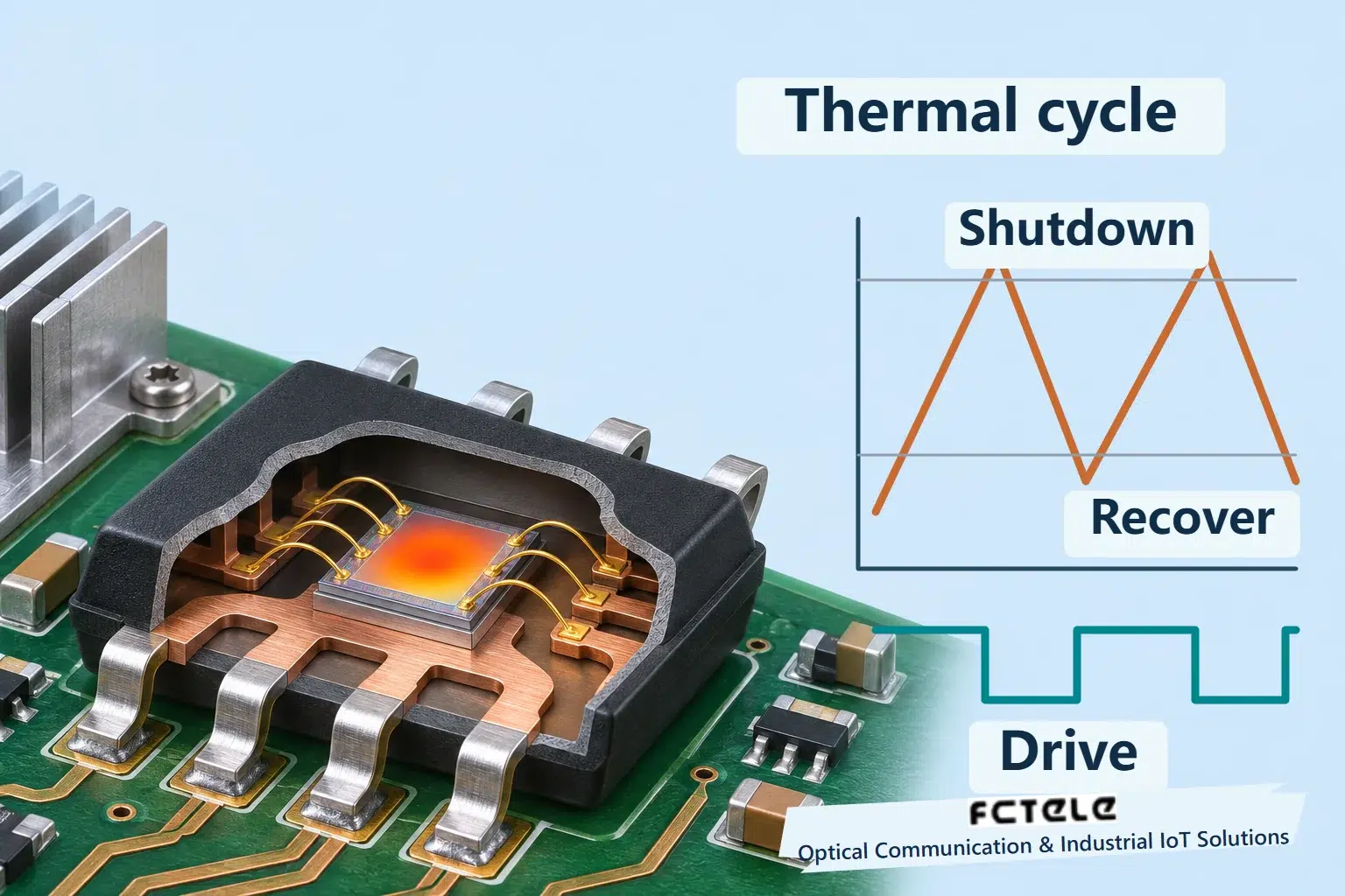
A persistent fault can restart the sequence
Follow a number-free example. An enabled driver encounters a persistent abnormal load, so output current is limited. If generated heat exceeds removal, junction temperature rises. Shutdown stops drive and the die cools. Recovery permits drive again. With the abnormal load still present, heating resumes. The conceptual plot shows this ordering, not a fixed diagnostic cycle or measured product behavior.
A returning signal may indicate only that an output stage has re-enabled. Receiving one byte does not establish a complete frame or application transaction. Separate supply continuity, logic enable, line output and valid responses when recording recovery. These observations must not be merged into one broad online indicator.
Other mechanisms also produce periodic symptoms, including upstream supply restart, application reconnection timers, intermittent contacts and enable conflicts. A repeating pattern supports a hypothesis requiring evidence. If the entire unit restarts, do not assign the cause directly to an RS485 chip; correlate external supply and system logs to locate the earliest abnormal event.
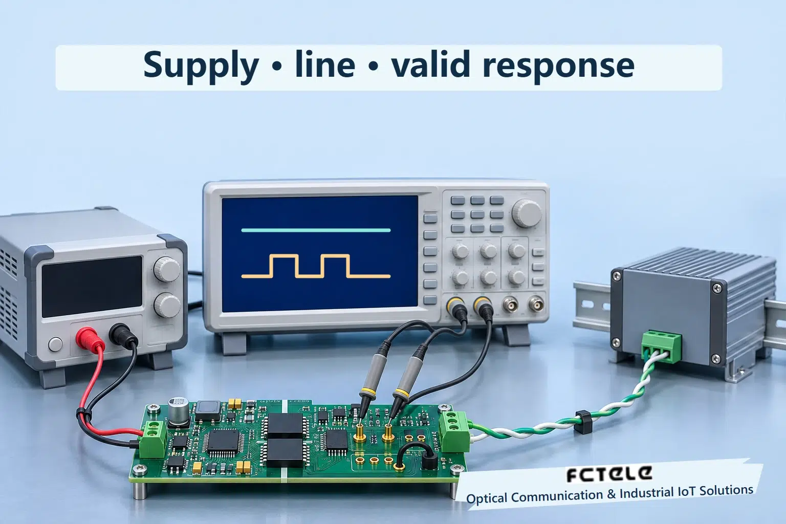
Verify evidence rather than repeatedly creating faults
Preserve connection relationships, node identity, serial settings and event times. Follow equipment procedures to arrange inspection of loose strands, damaged cable, termination and direction control. Do not create shorts on an operating bus or use external heating or excessive voltage to provoke protection. The bench illustration provides an observation context, not a fault-injection procedure.
Authorized testing can record supply, line output and communication separately. Retain instrument bandwidth, probe reference and sampling conditions. Average supply current is not an individual output transistor’s instantaneous current. Where internal junction temperature is inaccessible, explicitly record that it was not measured; an enclosure temperature must not be presented as a measured die-temperature trace.
Feichang’s one-RS485 plus one-RS232 fiber terminal is a real application example, but its delivered documentation governs protection and recovery. This article does not identify its transceiver or extend TI or Analog Devices current and temperature ratings to that equipment. An optical segment extends service; it does not repair shorted serial wiring, invalid voltages or bus contention at either end.
After repair, establish a known-good connection and verify sustained transfer, errors and complete application transactions. Retain one-change comparisons rather than replacing many items and losing diagnostic evidence. Limiting and thermal shutdown explain some abnormal behavior; reliable delivery still requires removal of the fault, permitted operating conditions and verified end-to-end communication.
Sources and scope
TI THVD1454 — section 8.4.3, protection · Analog Devices — current-limited driver · Feichang RS485/RS232 fiber terminal (Chinese)
Translated from the Chinese technical article: Read the original Chinese article.
Common questions
Does current limiting restore communication?
Not necessarily. Differential voltage can remain unusable; component protection is not correct data transfer.
Does repeated recovery prove thermal shutdown?
No. Supply restart, reconnection timers and intermittent contacts can also repeat. Verify separate evidence.
Does a cool enclosure exclude die overheating?
No. Surface and junction temperatures differ. State explicitly when junction temperature was not measured.
Further reading
RS485 receiver hysteresis · RS485 unit loads and driver budget
