

LASER / DIRECT MODULATION
Why establish a bias before modulating?
Bias establishes a laser operating point, while modulation produces rapid current changes that carry information. A low optical state can still emit light. Threshold, temperature and driver topology affect the relationship. The teaching diagrams provide no usable current settings. Average power monitoring cannot establish complete waveform quality or received-service performance.
01 · Threshold
Current establishes carrier and optical conditions; threshold depends on the device and environment.
02 · Bias and modulation
Bias sets an operating point. A modulation contribution changes current to carry symbols.
03 · Observe separately
Current, optical waveform and received service are distinct observation points.
Identify the design
Check the actual module, driver and applicable documentation.
Record the conditions
Keep temperature, supply and monitoring records together.
Correlate the result
Relate optical evidence to port errors and service records.
Selection and verification checklist — expand
| Check | Confirm | Evidence |
|---|---|---|
| Device | Exact implementation | Delivered documentation |
| Optics | Specified test conditions | Qualified waveform test |
| Service | Actual received data | Matching logs |
An optical port can emit light between business frames, and data transmission does not necessarily switch the source between complete darkness and maximum brightness. A directly modulated laser often separates two jobs: bias establishes an operating point, while modulation carries rapid changes. Follow current into the semiconductor and light into the fiber to understand the distinction.
Current injection and the onset of lasing
A laser diode is an active semiconductor device. Injected electrons and holes recombine in its active region and can release photons. At low injection, spontaneous emission dominates the explanation. These emissions do not by themselves establish the laser oscillation required by the design. Optical feedback allows suitable light to circulate and interact with the active medium. Once gain balances the relevant losses, stimulated emission becomes central to the output.
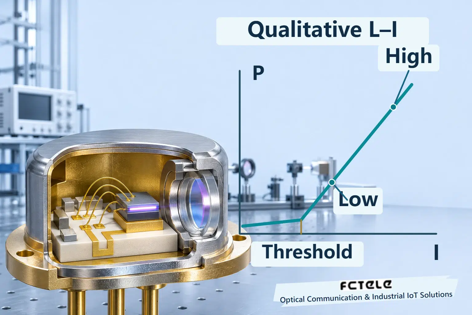
Threshold current describes the onset of lasing under specified conditions. It is neither a universal current nor an absolute boundary between no light and any light. Spontaneous emission can exist below threshold. Temperature, device construction and aging affect the characteristic, so a generic curve cannot prescribe an unknown module’s drive current.
The transmitter also includes a driver, supplies, optical coupling and protection. A lens and coupling structure deliver light into the core; the receiver processes what arrives. Similar housings do not establish identical lasers or monitoring circuits. This article addresses common directly intensity-modulated transmitters, not every externally modulated, coherent or pluggable implementation.
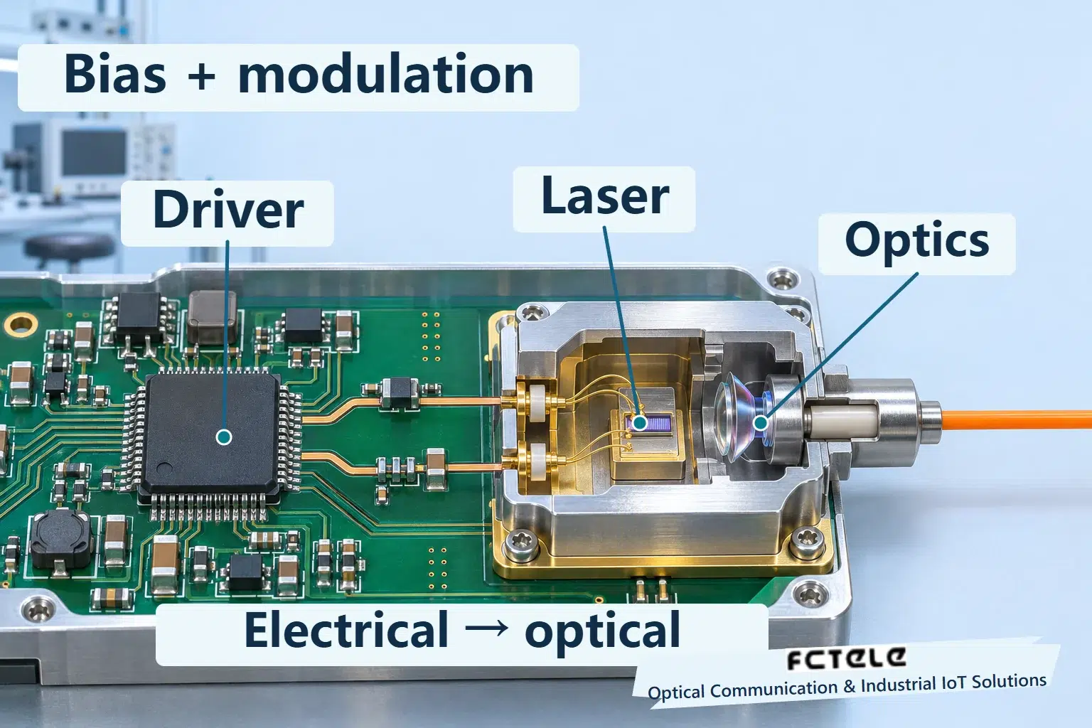
Bias establishes an operating point
Plot injected current horizontally and optical output vertically. The change around threshold reveals why the operating region matters. Above threshold, a useful range often shows a pronounced increase in optical power with current. This relationship is not an unlimited straight line: heating, ratings and other nonideal behavior impose limits. The illustration shows a qualitative shape without product parameters.
Bias places the device at the operating point selected by its design. Rebuilding carrier population and optical output from a low-injection state on every transition can introduce additional establishment behavior and dynamic effects. A suitable standing bias allows rapid modulation around planned conditions. Whether bias lies near threshold or higher, and how it changes, depends on the laser and driver.
More bias is not automatically better. It changes average output, low-state optical power, dissipation and heating, and can affect other transmitter metrics. Field maintenance must not adjust undocumented drive settings merely to raise a power reading. Internal settings involve matching and calibration; an adjustment the equipment does not expose is not a troubleshooting procedure.
Adding modulation creates distinguishable optical states
In a simple DC-coupled two-level teaching model, the low state uses the bias current and the high state adds a modulation contribution. The two current states produce different optical powers. The driver controls this current change; the drawing does not instruct users to connect arbitrary external supplies to laser pins.
Follow a number-free example. Place the low-state operating point in the intended region of the curve. A transition to the other state moves the current rightward and raises optical output. Returning low restores the original point. Both states can emit light. A receiver recovers symbols from changes; neither apparent brightness nor a single power-meter value substitutes for the transmitted waveform.
Real drivers use different output topologies and coupling arrangements. AC coupling introduces capacitors, low-frequency response and pattern conditions that the simplest addition diagram does not cover. The illustrations provide no soldering instructions, pinout or adjustable current value. They distinguish operating-point establishment from information-bearing change; device and equipment documentation govern implementation.
Temperature can change the current-to-light relationship
Threshold and the optical-output characteristic change with temperature. Holding injection current constant does not guarantee identical power in every environment. Some designs observe the transmitter with a monitor photodiode and adjust bias through a control loop. Automatic power control, or APC, has specific goals and implementation limits; its name does not imply that it repairs every waveform problem.
Maintaining average power also differs from maintaining fast optical changes. Modulation amplitude, edges, timing and noise cannot all be described by one average. Some designs separately compensate modulation current for temperature, illustrating the different jobs of bias control and the data path. Third-party chip documentation explains these roles without identifying any FCTELE product’s internal chip or control capability.
A diagnostic bias-current reading belongs with temperature, optical output and a historical baseline. One high reading does not establish laser failure, and current magnitudes should not rank unrelated models. A sustained deviation warrants further examination of supply, cooling, alarms and service results. A diagnostic page is neither a high-speed current probe nor permission to adjust the laser.
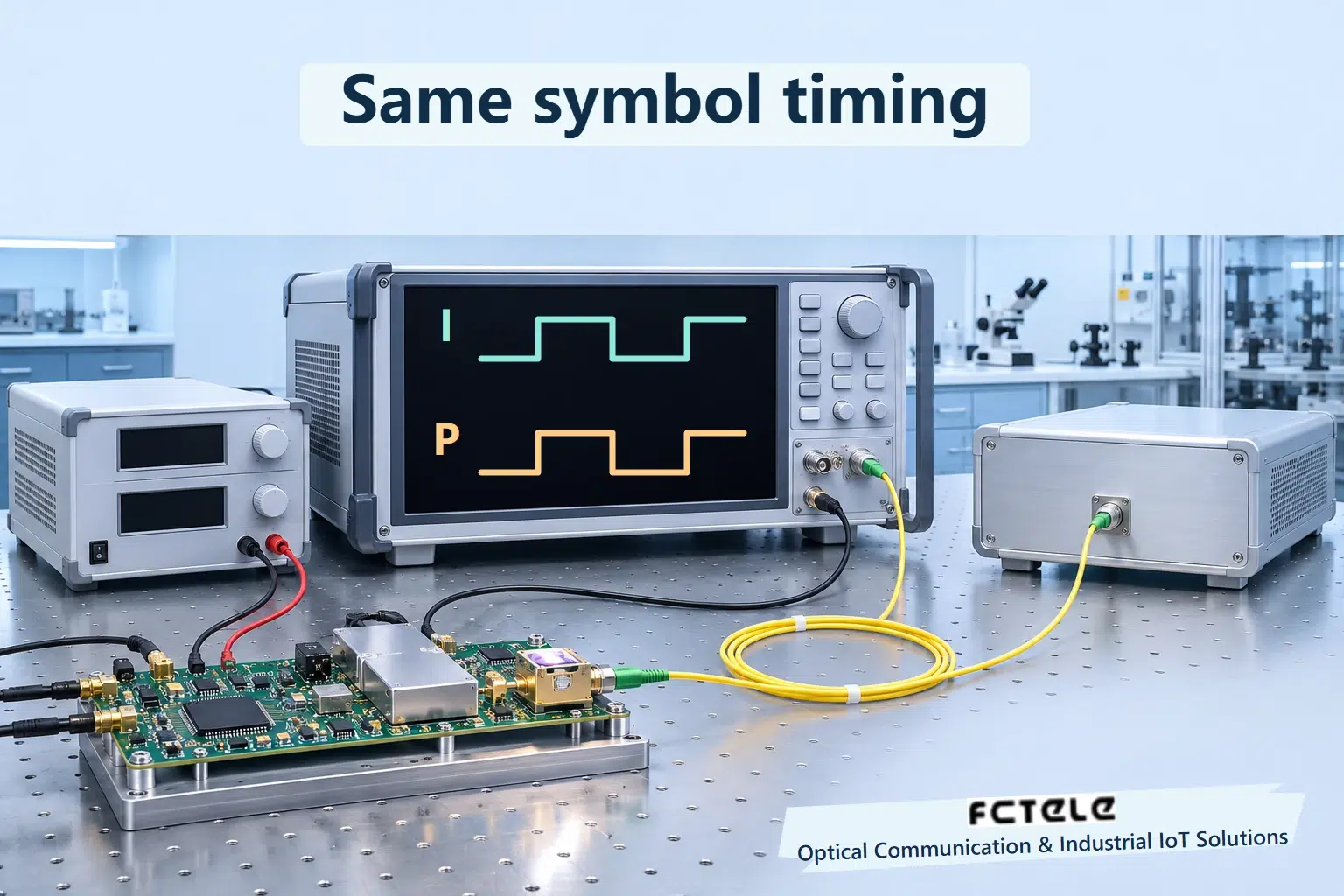
Relate operating conditions to signal evidence
An authorized test must identify its observation point: driver current, transmitted optical waveform or received service after the cable. These are different measurements. Readings from different places and times must not be presented as one synchronized experiment. High-speed optical measurements require instruments and methods matched to the interface and bandwidth; ordinary power meters do not automatically reveal edge or timing quality.
The Feichang website includes industrial switches with SFP ports and DDM management as real examples of host integration. Confirm compatible modules, diagnostic fields, firmware and operating conditions against delivered documentation. This article neither disassembles their lasers nor identifies a bias algorithm. TI and Analog Devices component parameters are not equipment specifications. All illustrations are generic mechanisms, not teardown photographs or measured results.
Handover records should retain host and module identity, temperature, supply conditions, diagnostic readings, port errors and actual request-response results. Correlation with one module or environmental condition is a lead for further testing. If a transmitter waveform requires verification, use a qualified test facility and the applicable method. Understanding bias and modulation helps interpret evidence; it does not authorize making a port brighter by bypassing its design.
Sources and scope
TI ONET4201LD — bias, data path and control · Analog Devices — bias and modulation · Feichang SFP/DDM switch (Chinese)
Translated from the Chinese technical article: Read the original Chinese article.
Common questions
Is more bias always better?
No. It changes output, dissipation and heating. Follow the device and equipment design.
Must the low optical state be dark?
No. A low state can emit light; average brightness is not a fast waveform.
Does a normal diagnostic reading prove waveform quality?
No. Monitoring, fast waveform and service results are different evidence.
Further reading
Optical extinction ratio · What a gigabit fiber port sends between frames
