


RS485 / RECEIVE DECISIONS
Why does the output retain its previous state?
A receiver with hysteresis switches at different input thresholds in the two directions. Inside that interval it preserves its previous output. This reduces repeated switching from small reversals near a threshold. The diagrams show a generic teaching model. Actual thresholds, guaranteed noise margin and operating limits require the device documentation.
01 · Stay low
Below the rising threshold, a low output is retained.
02 · Stay high
Above the falling threshold, a high output is retained.
03 · Track history
Inside the interval the same voltage can have different outputs.
Record both directions
Measure rising and falling switch points separately.
Keep the context
Record supply, reference, temperature and observation point.
Verify the system
Compare recovered logic with actual request-response results.
Selection and verification checklist — expand
| Check | Confirm | Evidence |
|---|---|---|
| Thresholds | Actual device limits | Delivered data sheet |
| Conditions | Permitted input range | Bench configuration |
| Results | Both trajectories | Input and output records |
A signal arriving at an RS485 fiber terminal is not a perfectly straight set of voltage steps. Edges and interference can move it back and forth near a decision point. A receiver with only one threshold could turn those small movements into repeated output transitions. A receiver with hysteresis uses different thresholds for the two switching directions. Small reversals preserve the existing state until the input crosses the other threshold.
Follow the copper input into the device
An RS485 receiver responds to the voltage difference between two signal conductors. Here Vd means the difference calculated in the selected polarity. A and B names can vary between equipment, so use the electrical definitions in the delivered documentation. The receiver converts its differential input into a digital decision that subsequent serial or internal logic can process.
Subtracting the conductor voltages reduces some interference that affects both similarly. This is common-mode rejection. If the interference affects the wires differently or directly changes their difference, the differential input still moves. Twisted pair therefore does not make a receiver immune to noise. Attenuation, reflections and reference conditions require their own checks, and garbled characters do not identify one of those causes on their own.
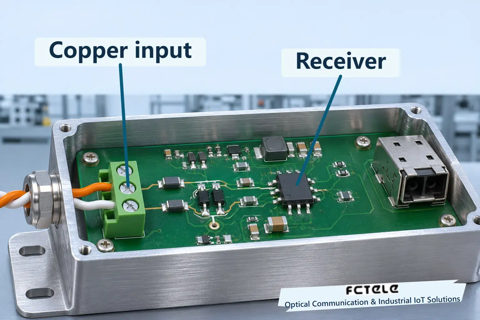
Inside a serial fiber terminal, the copper input passes through the product’s protection and receive circuitry before recovered logic enters subsequent processing and optical transmission. Hysteresis belongs to the receive decision, rather than a filter inside the fiber. The illustration enlarges only the copper receive direction. It does not identify a Feichang chip or show an actual product teardown.
Why one threshold can cause chatter
Consider an ideal comparator with its single threshold at zero. A negative input rises slowly toward positive values while a small disturbance is superimposed. Near zero it may become positive, negative and positive again. A decision based only on its instantaneous sign produces repeated transitions, potentially creating extra edges for the following digital logic even though the transmitter did not intend them.
This example does not predict that every slow edge will cause an error. Real devices have bandwidth, delay, thresholds and specified operating conditions. The point is that, near a switching point, a small disturbance can be converted into digital activity unless some mechanism limits repeated switching. An illustrative spike is not proof of an erroneous character in an installed system.
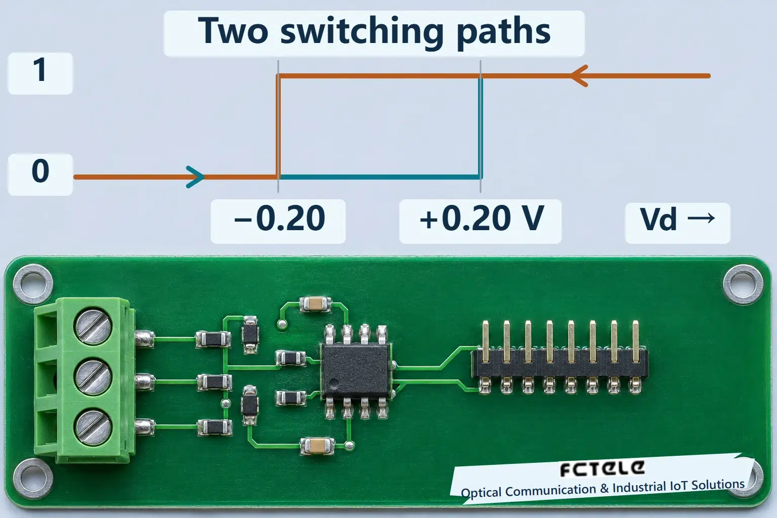
With hysteresis, the threshold that changes a low output to high differs from the threshold that changes high to low. Between them, the previous state is retained. The same instantaneous input can therefore produce either state depending on its earlier trajectory. This state dependence does not mean the receiver stores a serial message.
Walk through five input values
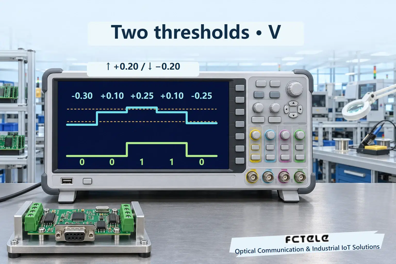
Assume an ideal teaching model with a rising threshold of +0.20 V and a falling threshold of −0.20 V. These symmetric thresholds are neither universal RS485 values nor Feichang specifications. Actual transceivers can shift both thresholds for functions such as fail-safe reception. Check the guaranteed hysteresis, conditions and temperature range in the relevant data sheet.
Start with a low output and apply −0.30, +0.10, +0.25, +0.10 and −0.25 V in that order. The first value is below the falling threshold and the output is low. The second is positive but remains below the rising threshold, so the output stays low. The third exceeds the rising threshold and produces high. Returning to +0.10 V at the fourth point preserves high. Only the fifth point falls below the falling threshold and returns the output to low. The output sequence is low, low, high, high, low.
The second and fourth points have exactly the same +0.10 V input but different outputs. A lookup based on voltage alone cannot explain them without prior state and direction. The illustration separates input and output rows on a common time axis, with dashed lines for both thresholds so corresponding moments can be compared.
The difference between thresholds is the hysteresis width, 0.40 V in this model. It is not the permitted common-mode range or driver swing, and it does not certify system noise immunity. Increasing the width changes the input excursion needed to switch. It must be considered with sensitivity, signal margin and required rate rather than treated as a value to maximize without qualification.
Hysteresis, idle bias and termination have different roles
Hysteresis helps preserve a state during a small input reversal near the thresholds. Idle bias concerns the electrical conditions when no driver is transmitting. Some devices have integrated fail-safe behavior, and the overall bus still depends on the equipment design. A hysteresis specification does not establish a fixed output for every open circuit, short circuit, power-up or idle condition. It also does not justify adding bias resistors at every node.
Termination addresses reflections at transmission-line ends. Significant ringing still requires checking the cable, topology and termination. Hysteresis cannot repair a broken conductor or make an input outside its common-mode or absolute ratings safe. Bias and termination changes also alter loading and signal levels, so check existing circuitry and permitted configurations before making changes.
A stable digital output does not prove a complete Modbus transaction is correct. UART format, addresses, frame checking, direction control and application processing remain downstream. Relate the electrical input, recovered logic and actual request-response behavior to distinguish receive chatter from faults at those other layers.
Turn the mechanism into checkable evidence
On an authorized bench, use a suitable differential source, load and instruments within documented operating limits. Record the switching point separately while raising and lowering the input. Include supply, reference potential, temperature, ramp rate and observation location. Do not inject arbitrary voltages at unknown terminals or open production equipment to reach undocumented test points. Use the manufacturer’s method when internal points are unavailable.
Feichang’s DIN-rail terminal carrying one RS485 and one RS232 channel provides a real serial-access example. Its receiver implementation, hysteresis width and accessible diagnostics require the delivered documentation. This article explains generic behavior without transferring a TI chip specification to a Feichang product. Each copper segment on either side of a fiber extension retains its own receive and termination conditions.
For a field comparison, keep the devices and configuration fixed while substituting a known-good short lead. Record counters, received bytes and application results, then restore the installed wiring in stages. Testing hysteresis itself needs traceable input and output observations. A computer log cannot reconstruct analog thresholds. Separate rising and falling records establish more than a single successful reception.
Sources and scope
TI SLLA322 — receiver hysteresis · Feichang RS485 and RS232 fiber terminal (Chinese)
Translated from the Chinese technical article: Read the original Chinese article.
Common questions
Does the voltage alone determine the output inside the interval?
No. The previous output and input trajectory matter.
Are ±0.20 V universal RS485 switching thresholds?
No. They are a symmetric teaching model. Actual thresholds require the relevant device documentation.
Does hysteresis replace termination and idle-state design?
No. Threshold state retention, reflection control and undriven bus conditions have different roles.
Further reading
How 10BASE-T recovers timing · What a gigabit fiber port sends between frames
