

INDUSTRIAL CONNECTIVITY / 4G AND 5G REDCAP
Which interfaces and recovery checks does your equipment need?
Select by local Ethernet, fiber, serial and I/O requirements, then verify the cellular version against the available network. F2B1 and F5 offer different interface combinations. The illustrated sites are examples, not industry restrictions. An active network connection does not by itself prove correct values, remote reachability or application recovery.
01 · Allocate the resource groups
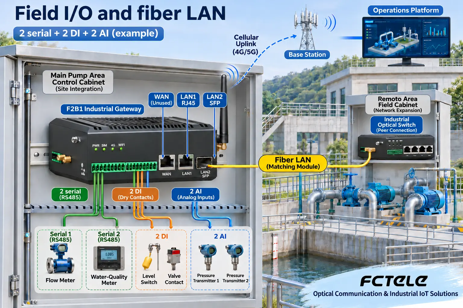
F2B1: two serial groups plus one 2-DI and one 2-AI group use all four groups. Optical LAN2 extends the local network.
02 · Map the four LAN ports
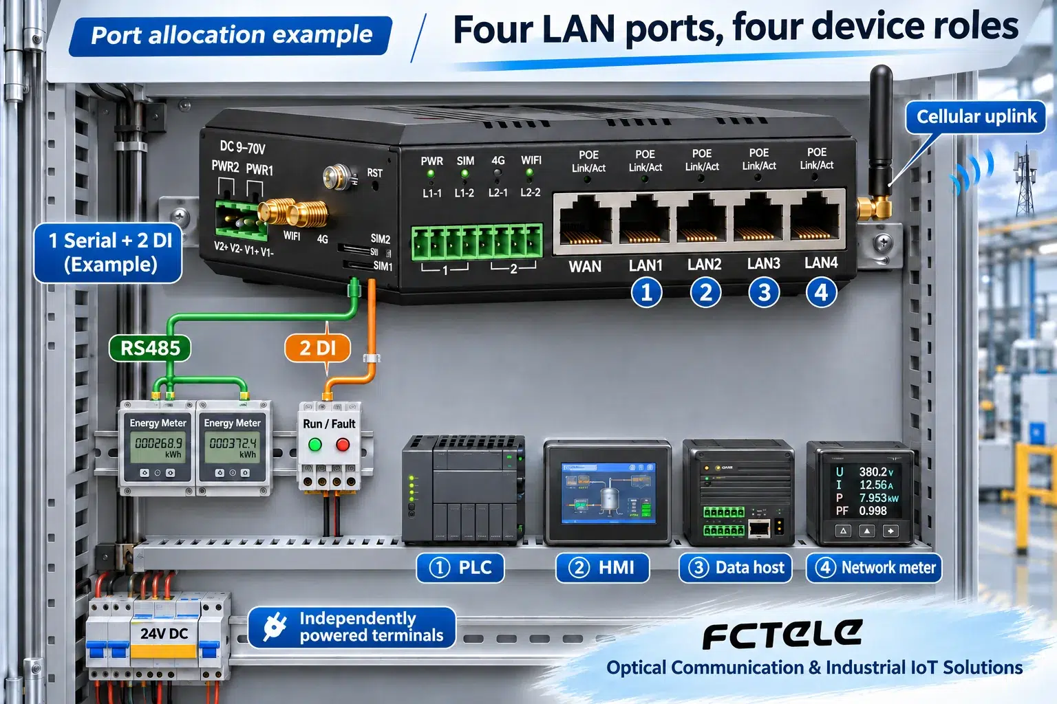
F5: identify each terminal and its LAN port. Count extra terminals and traffic before deciding whether another switch is needed.
03 · Verify new application data
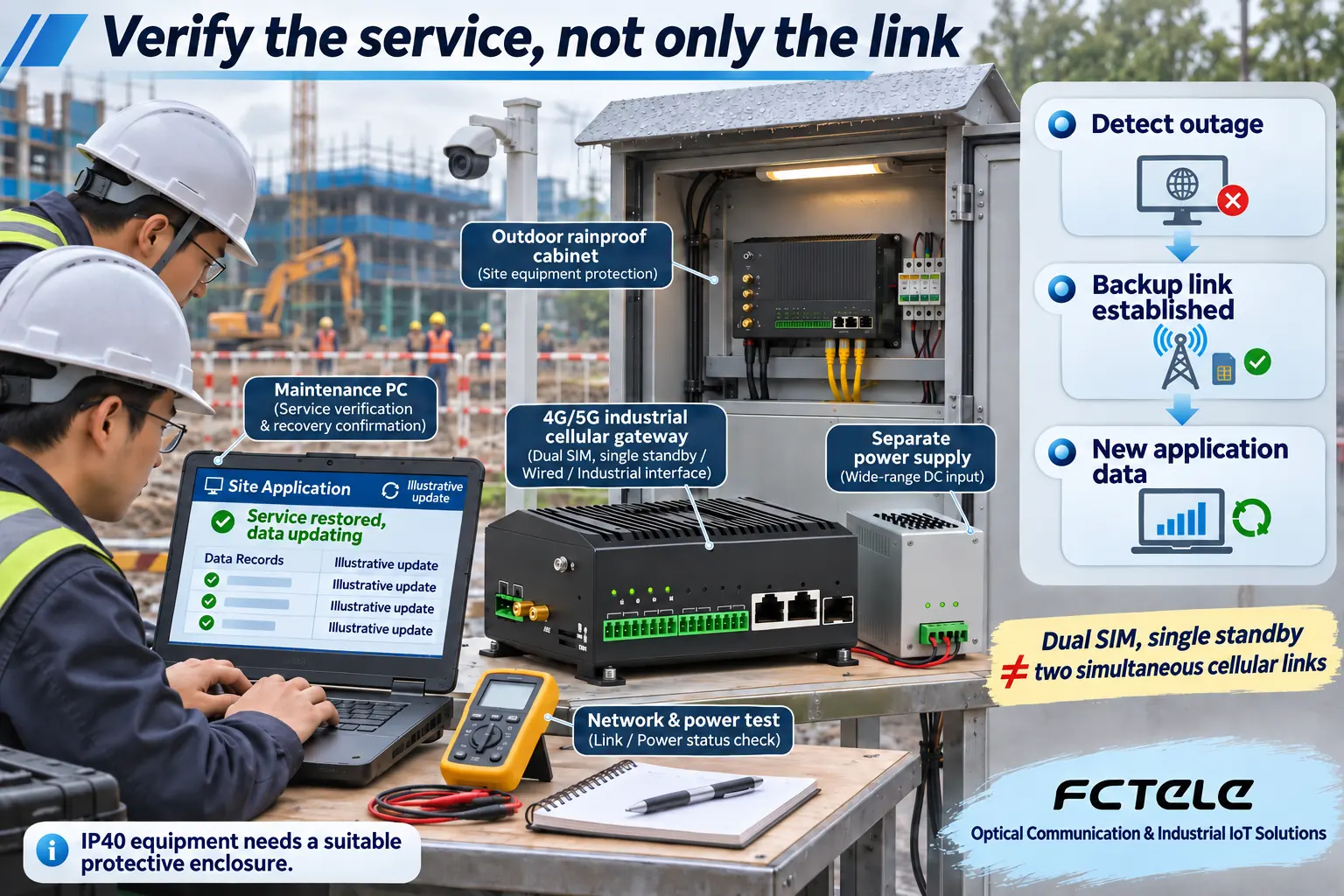
A backup connection is one recovery stage. Record when sessions reconnect and fresh readings reach the platform.
Confirm the point list
Match electrical types, data interpretation and ordered resource groups.
Confirm connectivity
Check LAN endpoints, matching optics, operator support and access policy.
Confirm the workflow
Compare local values, platform fields and new data after a controlled outage.
Selection and verification checklist — expand
| Check | What to confirm | How to verify |
|---|---|---|
| Interfaces | Ports, resource groups and power options | Order configuration and per-point connection list |
| Cellular | Version, bands, coverage and service | Operator confirmation and actual site trial |
| Recovery | Connection and application are separate observations | Record outage, reconnection and first fresh value |
When industrial equipment needs connectivity, instrument readings need to reach a platform, or field terminals need remote maintenance, start with interfaces, data protocols and network conditions rather than an industry label. FCTELE FCT-6300-F2B1 and FCT-6300-F5 industrial cellular gateways combine Ethernet, serial or acquisition interfaces, and a 4G or 5G RedCap uplink. Their suitability depends on matching those capabilities to the equipment. This guide covers I/O and fiber-LAN aggregation, multiple Ethernet terminals, and primary or backup cellular access. Pumping facilities, equipment cabinets and temporary sites are illustrations, not restrictions on use.
Compare the two configurations
| Requirement | FCT-6300-F2B1 | FCT-6300-F5 |
|---|---|---|
| Local network | 1 copper WAN + 1 copper LAN + 1 SFP LAN | 1 copper WAN + 4 copper LAN; no SFP |
| Configurable resources | 4 groups: each 1 serial or 2 same-type I/O | 2 groups: each 1 serial or 2 same-type I/O |
| Example allocation | 2 RS485 + 2 DI + 2 AI; all 4 groups | 1 RS485 + 2 DI; both groups |
| Cellular version | 4G Cat.4 or 5G RedCap | 4G Cat.4 or 5G RedCap |
| PoE | Not provided | Optional PSE output; 48–55 V DC input when enabled; confirm total budget |
| Requirement emphasis | More field points and local fiber extension | Multiple Ethernet terminals together |
All listed Ethernet interfaces are 100 Mbps. Serial and I/O maxima are alternatives within the shared groups, not additive capacities. Confirm the ordered configuration.
Start with the connectivity requirements
Customers usually need more than a box that can access the Internet: they need field devices to fit an existing operating workflow. A monitoring application needs readings delivered correctly; an equipment manufacturer wants a clear integration and maintenance arrangement; a site without fixed broadband needs a suitable communications path. Ethernet port count, local fiber connectivity and signal types help determine the better starting point.
The F2B1 provides one copper WAN port, one copper LAN port and one 100 Mbps SFP LAN port. It suits requirements that include extending the local network over fiber. Four configurable resource groups each provide either one serial interface or two I/O channels of the same type. The F5 provides four copper LAN ports and one copper WAN port for multiple Ethernet terminals. Its two resource groups provide up to two serial interfaces or four I/O channels, with substitution by group.
Both models are offered in 4G Cat.4 and 5G RedCap versions. First decide how equipment connects locally, then select the cellular version and antenna arrangement. The F2B1 optical interface is a LAN port, not a confirmed fiber WAN interface. Multiple F5 LAN ports also do not automatically mean separate security zones; check the actual isolation and configuration capabilities required by the project.
Requirement 1: aggregate field data and extend the LAN over fiber
This requirement can arise in manufacturing equipment, energy metering or environmental monitoring, subject to the interfaces, protocols and installation conditions. Consider a pumping facility purely as an example. It needs flow and water-quality readings, a level switch, a valve status contact and two pressure measurements. A second equipment area already has network devices and needs a fiber connection to the main cabinet. For this combination, the F2B1 offers a useful starting point: two groups configured as RS485 for instruments, one group as two digital inputs (DI), and one group as two analog inputs (AI).
Two serial interfaces plus four I/O channels occupy all four resource groups. Combining instrument communications and direct acquisition can reduce the number of separate interface handoffs between serial-networking devices, acquisition modules and the router. Whether one unit can implement the complete requirement still depends on electrical signal conditions, supported protocol modes and field loads. The maximum of four serial interfaces cannot be added to the maximum of eight I/O channels.
A matching optical device in the second area connects through the F2B1 LAN2 optical port, while the cellular module provides the wide-area connection toward the remote platform. Fiber extends the local network; RS485 and AI obtain business values; the platform associates them with named measurement points. Planning these roles separately avoids treating copper distance, instrument protocols and cellular access as one interchangeable issue.
Follow the complete data path. An instrument may provide a raw register value using Modbus RTU. A supported operating mode then acquires or converts the value and sends the agreed MQTT topic and JSON field to the platform. As an illustrative calculation, a register value of 1234 with a documented multiplier of 0.1 represents 123.4 engineering units. The instrument manual and point list determine the unit, data type, byte or word order and multiplier. Seeing a number on a dashboard does not prove that those interpretations are correct.
Requirement 2: connect multiple Ethernet devices
An equipment supplier may need a PLC, a human-machine interface (HMI), a data-acquisition host and a network instrument connected in one assembly. The F5 provides four LAN connection points for these four terminals. Its WAN port can connect to a site network, with cellular access providing another uplink according to the supported configuration. Whether a separate switch is still required depends on total port demand, traffic load and isolation requirements. The illustration shows a cellular-uplink example with WAN unused, rather than requiring that arrangement for every installation.
The two acquisition resource groups can be ordered as one RS485 interface plus two DI channels: serial communications for instruments and digital inputs for running and fault contacts. Mark network-derived information and directly acquired terminal signals separately in the point list. This gives the equipment manufacturer an identifiable relationship between ports, channels and platform variables, rather than only a SIM-card access point, and helps maintenance personnel locate a changed terminal later.
The immediate value is clearer integration and maintenance, not an unmeasured percentage saving. The Ethernet ports are 100 Mbps, and a cellular module’s theoretical peak rate is not the actual throughput of an individual Ethernet port. If video, firmware transfers and device data run together, test the required concurrent load. The four illustrated Ethernet terminals have independent power supplies; plugging in a cable does not establish that PoE power is available.
If the application needs Power over Ethernet (PoE), check the F5 optional power sourcing equipment (PSE) output, supply voltage and total power budget. Enabling that output requires a 48–55 V DC input according to the product information. PSE means supplying power to external equipment, not receiving power through a network port. The F2B1 does not provide PoE. Confirm this difference before ordering to avoid a power-system mismatch on site.
Requirement 3: cellular access and backup-path recovery
A missing fixed broadband connection or a need for backup access is not confined to temporary sites. A temporary monitoring or commissioning location is one example. Where coverage and service-plan conditions permit, cellular access can establish a path for data reporting and authorized remote maintenance. The choice between F2B1 and F5 still follows local fiber, Ethernet and acquisition needs; a short deployment does not remove the need to plan interfaces.
The public product information lists wired/cellular backup, dual-SIM single-standby operation, online detection and reconnection functions. Single standby must not be read as two simultaneously active cellular paths. An available backup path also does not establish seamless application recovery. Fault detection, connection setup, address changes and application-session rebuilding are different stages. Confirm that the platform receives new data after the path is restored.
A controlled disconnection test makes the acceptance criteria concrete. Record when the original path fails, the backup connection is established, the application reconnects and a new reading arrives. Include buffering or historical retransmission only when the specific operating mode explicitly supports it. A current value received after recovery is not evidence that the complete history was recovered. For remote commands, verify handling of expired or repeated operations; retain critical interlocks in an appropriate local control system.
The equipment is IP40, so an exposed installation requires a suitable protective enclosure and environment. Place antennas according to actual signal conditions rather than hiding them behind metal and relying only on signal bars. Plan power, grounding, cable retention and maintenance access together. The benefit of deployable cellular access comes from a clear installation and verification process, not a promise of connectivity at every location.
Choose 4G or 5G RedCap from the network and workload
RedCap is a reduced-capability direction within 5G intended for appropriate device requirements. It is not interchangeable with every 5G service, the highest possible speed or deterministic control. For these products it is a version choice. Verify local support, frequency bands, SIM service, operator provisioning and the antenna arrangement. Where coverage is established and the workload is mainly status and instrument data, evaluate 4G Cat.4 first. Where RedCap availability and an upgrade requirement are confirmed, evaluate the corresponding version.
Distinguish outbound reporting from inbound maintenance access. A gateway initiating a platform connection does not prove that a computer on the public Internet can directly reach a PLC. Operator addressing and access policies may restrict inbound traffic. Design any APN or private-network service, supported remote channel and permissions for the project. Port forwarding, NAT or a VPN name alone is not a security guarantee; do not broadly expose control interfaces for convenience.
Use a requirements sheet to obtain the right configuration
Before requesting a configuration, list location and operator network, Ethernet terminal count, local fiber requirements, serial electrical standards, DI/DO/AI/AO types and quantities, platform protocols and update requirements. State optional Wi-Fi, eSIM or PoE requirements explicitly rather than assuming all series options are standard. Confirm the optical module rate, fiber type and matching device at the far end.
Commission in three steps: compare local raw instrument values with engineering values; verify platform topics, fields and update times; then test the required paths and recovery behavior. Save the channel list, configuration backup, software version and test conditions so the process can be repeated for another deployment. Select the appropriate interface combination and deliver equipment access together with the remote workflow, rather than accepting an illuminated network indicator as the entire result. These are typical application designs, not records of an implemented customer project or measured business results.
Product evidence and scope
Interface and option statements were checked against the manufacturer product information on 22 November 2026. The following detailed configuration pages are in Chinese.
FCT-6300-F2B1: SFP LAN and four configurable groups
FCT-6300-F5: four LAN ports and two configurable groups
Confirm the actual model, firmware, signal electrical conditions, operator network and order options. Example applications do not establish completed customer deployments or measured savings.
Translated from the Chinese technical article: Read the original Chinese article.
Common questions
Which model suits instrument acquisition plus a local fiber connection?
Start by evaluating the F2B1 SFP LAN and four configurable groups. Confirm optical modules, protocols and electrical signal types. Two RS485 interfaces plus two DI and two AI channels use all four groups; do not add the separate maximum capacities.
Does an F5 with four network terminals still need a switch?
Its four LAN ports provide local connection points. Additional switching depends on total terminals, 100 Mbps traffic load and isolation needs. The example uses independently powered terminals; optional PoE is a separately confirmed PSE output.
Does choosing 5G RedCap guarantee interruption-free remote control?
No. Check local RedCap support, version, bands and operator conditions. Recovery includes detection, connection establishment, sessions and new data. Dual-SIM single standby is not simultaneous dual-cellular operation; retain critical interlocks locally as required.
Further reading
4G gateways versus industrial routers · LoRa and 4G point mapping and control feedback
