


DIGITAL INPUTS / CONTACT BOUNCE AND ACCEPTANCE
What counts as one valid switch operation?
Mechanical contact, accepted input state and application event are different observations. Debouncing applies a stability rule, adding delay and potentially rejecting short pulses. Verify the supported input conditions, the rule actually implemented and the application counting method. Three samples below is a teaching example, not a claimed FCTELE product setting.
01 · Separate contact and message
A rebounding contact creates several electrical transitions. That does not establish duplicated communication.
02 · Require stability evidence
In this example, three opposite samples accept a new state. A sample matching the accepted state resets the candidate.
03 · Preserve useful pulses
The short pulse is absent from the accepted trace. The longer pulse appears later. Define valid pulse widths before filtering.
Observe the source
Match electrical conditions and time resolution at a permitted test point.
Walk through the rule
Compare all nine raw samples with accepted state and counter resets.
Check the event
One accepted rising edge and repeated high-state scans are different counting inputs.
Selection and verification checklist — expand
| Check | What to confirm | How to verify |
|---|---|---|
| Input | Electrical type and documented pulse conditions | Actual model and controlled stimulus |
| Acceptance | Filter behavior and latency reference | Raw versus accepted traces |
| Application | One event per intended operation | State, edge and event records compared |
A limit switch operates once, yet the event log shows on, off and on. Do not immediately conclude that the fiber link duplicated a message. Mechanical contacts can briefly separate after touching, and a sufficiently fast input can detect several electrical edges during one physical operation. Debouncing accepts a state according to a defined stability rule; it does not arbitrarily delete every short pulse. Separate raw contact behavior, accepted input state and application events to understand the result.
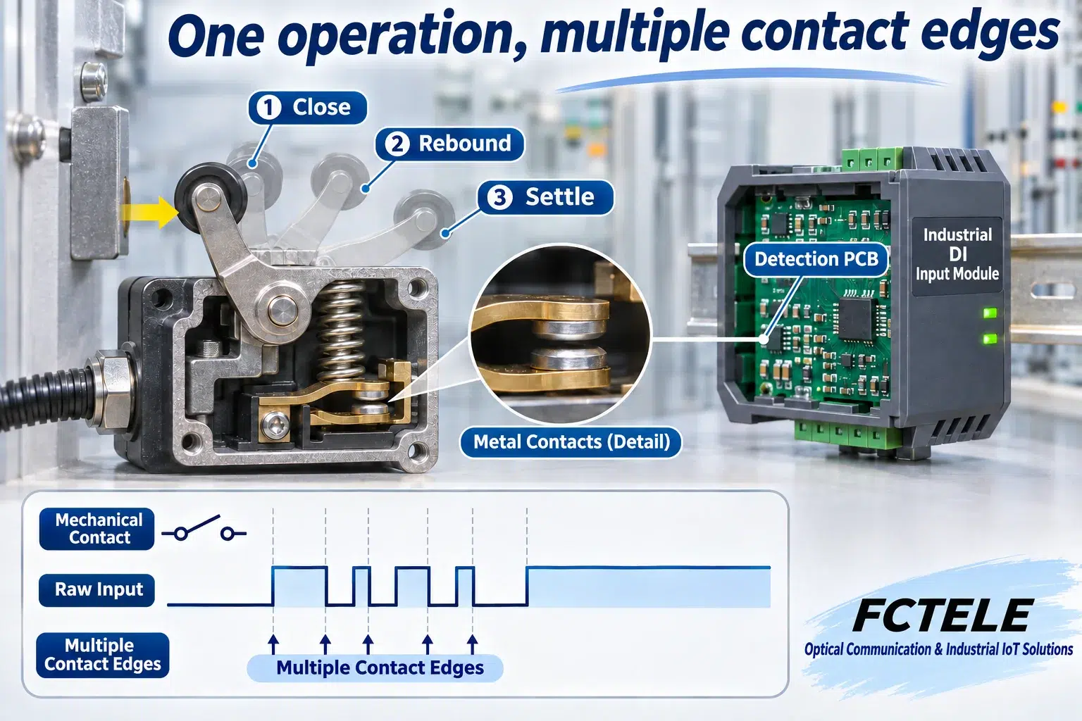
One mechanical operation can create several electrical edges
A moving arm and fixed contact establish or break a circuit. The elastic mechanism can rebound after impact and alternate between contact and separation before settling. Release can produce similar behavior. The operator experiences one movement while the detector sees several intervals of different duration. This is a different cause from software transmitting a message twice.
A digital input first converts electrical terminal conditions into logic levels. A dry contact does not itself supply voltage: the matching input circuit establishes the detection conditions. Powered inputs also require voltage, polarity and reference checks. Do not treat a conceptual switch drawing as a universal DI wiring diagram or test unknown terminals with an external supply. If a transient crosses the actual detection threshold and is not suppressed elsewhere, downstream logic may observe an extra edge.
The public information for the FCTELE FCP-K16G discrete-I/O fiber terminal lists input filtering. This provides a real remote-I/O application context, but the implementation, timing and minimum valid pulse width must be checked against delivered documentation. The following explanation is a generic mechanism, not that product’s internal circuit, and its example values are not FCTELE specifications.
Electrical filtering and state acceptance wait for different evidence
One hardware approach uses a resistor-capacitor response before detection so a very brief input change cannot immediately produce an equally large voltage change at the sensing node. A suitable decision circuit then restores a clear digital state from the slowly varying voltage. A capacitor does not identify the intended operation: its charge and discharge follow circuit conditions. Component values, input leakage and switching thresholds affect the result.
Another approach evaluates persistence after digitization. When the raw state first differs from the accepted state, it becomes a candidate. The system updates the accepted state only after the specified stability condition is satisfied. A return to the existing accepted value cancels that candidate. A timer, configurable logic or software can implement this type of test. Approaches can be combined; the word ‘filter’ on a product description does not identify its exact internal design.
Hysteresis is also different from time-based debouncing. Different thresholds for opposite directions can constrain small voltage excursions near a switching point. Time-based debouncing requires evidence that a state persists. A contact that physically opens and closes may cross the entire threshold band, so hysteresis alone need not suppress every extra change. Identify the disturbance before choosing where and how to process it.
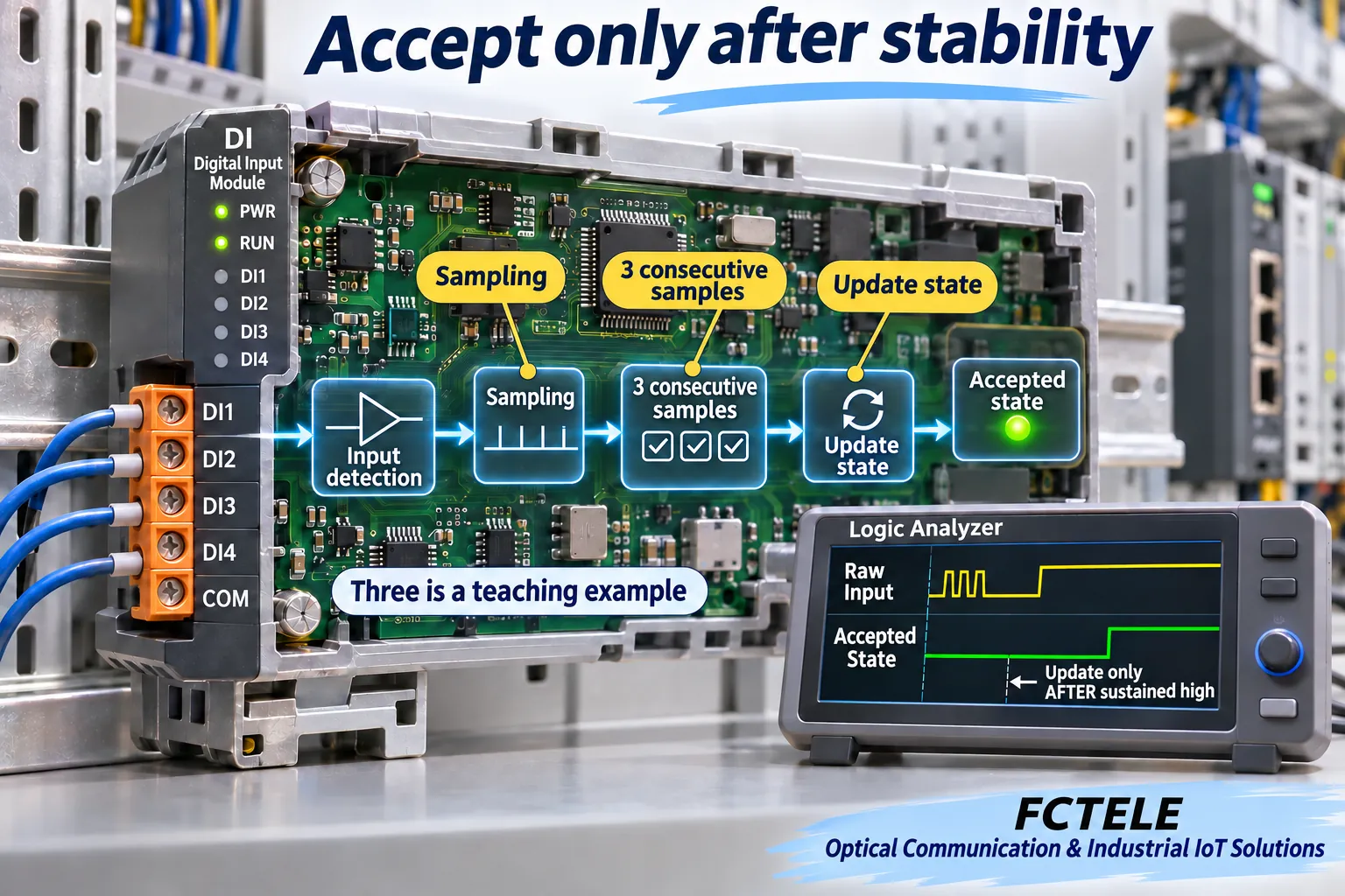
Follow nine samples through one acceptance rule
For this teaching example, the accepted state initially equals 0. Sample at regular intervals and accept the opposite value only after three consecutive samples differ from the current accepted state. A sample equal to the accepted value resets the candidate counter. This is neither majority voting nor a rule to toggle at every third arbitrary edge. The interval and count are illustrative, not settings claimed for a particular product.
Consider raw samples 0, 1, 0, 1, 1, 1, 0, 0, 0. The first sample requires no update. The second creates candidate 1 with count 1; the third returns to 0 and cancels it. Samples four to six are consecutively 1, so the candidate count reaches 1, 2 and 3. Only at sample six does the accepted state become 1. Samples seven to nine are consecutively 0, and 0 is accepted at sample nine.
The accepted sequence is therefore 0, 0, 0, 0, 0, 1, 1, 1, 0. Several raw changes become one accepted high interval. An application counting accepted rising edges increments once for this sequence. An application incrementing on every scan that reads high can still count repeatedly. Input debouncing and application-event generation must work together; repeated records do not always originate at the contact.
Stronger filtering can reject a valid short pulse
Three consecutive samples do not imply a fixed delay of exactly three complete sample periods from the mechanical operation. The operation’s phase relative to sampling affects the first observation, and the final settling time is not fixed. State the timing reference: first terminal transition, last rebound or accepted-state update. Delays measured from different references cannot be compared directly.
A genuinely valid pulse appearing in only one or two samples would also be rejected by this example. A sequence of logic levels does not reveal whether the pulse is unwanted bounce or useful process information. Define what has business meaning first. Level confirmation, access events and high-speed counting can have different pulse-width and latency requirements and should not automatically share one untested setting.
Input filtering, internal sampling, communication, controller scanning and event logging are separate stages. Fast optical-path recovery does not prove equally short contact-to-application latency. Slower host polling does not establish stronger input debouncing. Low-rate logs may already miss short changes; their absence does not prove a bounce-free raw signal.
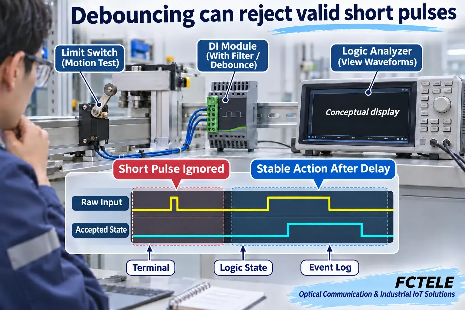
Verify both suppression and preservation of useful signals
On an authorized test bench, distinguish the observation points: raw input at the terminal or documented test point, accepted state where the interface exposes it, and application-event records. Match instrumentation to the electrical conditions, time resolution and grounding arrangement. When internal test points are unavailable, use manufacturer-supported methods rather than opening equipment or injecting signals into unknown terminals.
First use a stable input to confirm channel, polarity and mapping. Repeat contact operations and compare raw changes with accepted states. Then compare short and long pulses within the application’s permitted test conditions. Record which pulses are accepted, when updates occur and how many events one valid operation generates. If filtering is adjustable, change one setting while keeping supply, stimulus and recording conditions constant. The illustrations are teaching diagrams, not measured test reports.
Identify where timestamps are created. A platform reception timestamp includes transmission and queuing; a device acceptance timestamp still includes the earlier confirmation interval. Both can be useful, but neither automatically identifies the contact’s first mechanical impact. Use the same observation definition when comparing arrangements and include it in the acceptance record.
Test startup, input disconnection, optical loss and communication recovery separately. Debouncing does not repair wiring or validate the loss-of-link output strategy. A normal remote-I/O device does not become a certified safety input simply because it filters signals. Save input type, firmware, filter setting, test conditions and results so maintenance personnel know which stage was verified, rather than merely reporting that an indicator stopped flickering.
Sources and scope
TI SCEA094: Debounce a Switch · Microchip AN2805: debouncing background · FCP-K16G product documentation (Chinese).
Generic mechanisms and teaching values do not identify a particular product circuit, algorithm or pulse-width capability. Verify actual electrical conditions, filtering and timing against delivered documentation.
Translated from the Chinese technical article: Read the original Chinese article.
Common questions
Does three-sample confirmation mean exactly three sample periods of delay?
No. Operation phase, the first observed change and counter resets affect acceptance time. State the measurement reference.
Can repeated application events after debouncing be blamed directly on the contact?
No. Counting on each high-state scan can repeat even for a stable signal. Distinguish accepted state from one rising-edge event.
Can a fiber I/O terminal with filtering be assumed suitable for high-speed counting?
No. Filtering may reject short pulses. Check minimum valid pulse width, response and the complete channel requirements against the actual model.
Further reading
Testing contact-over-fiber links · Discrete versus analog fiber I/O
