


UART PARITY, AT A GLANCE
Can a byte be wrong even when parity passes?
Yes. Parity checks only whether the total number of ones in a character’s data and parity bits is odd or even. An even number of flipped bits can preserve that total’s parity while changing the byte. A later network check covers the newly encapsulated frame, so it cannot prove the earlier serial content was correct. Check the format, implementation and application rules separately.
Count the right bits
Even parity counts data bits and the parity bit, not start and stop bits.
Recognize the blind spot
Two flips can leave the parity unchanged. A pass is not proof of identical content.
Follow the evidence
Error handling and later encapsulation depend on the actual implementation.
Compare formats
Record baud rate, data bits, parity and stop bits at every serial endpoint.
Locate diagnostics
Check where error flags originate and whether firmware retains or exposes them.
Compare actual bytes
Use known content and timestamps; distinguish display encoding from byte changes.
Selection and verification checklist — expand
| Check | What to confirm | How to verify |
|---|---|---|
| Character format | Identical endpoint settings | Read both configurations and save the complete format. |
| Error policy | Discard, retention and reporting | Consult model documentation and run a controlled test. |
| Observation point | Raw bytes versus display text | Preserve hexadecimal bytes, flags and timestamps. |
| Application scope | Message boundaries and checks | Follow the actual protocol’s length, sequence and timeout rules. |
| Model capability | Supported formats and diagnostics | Verify current official documentation for the exact model. |
Conceptual diagrams, not measurements or a particular product’s internal circuit.
Serial settings often offer None, Odd and Even parity. Does choosing even parity guarantee correct data? No. It gives each character a small consistency check. The check can detect some errors, but it does not know the original content. To use it well, first understand its scope, then follow the data through the equipment and look for evidence.
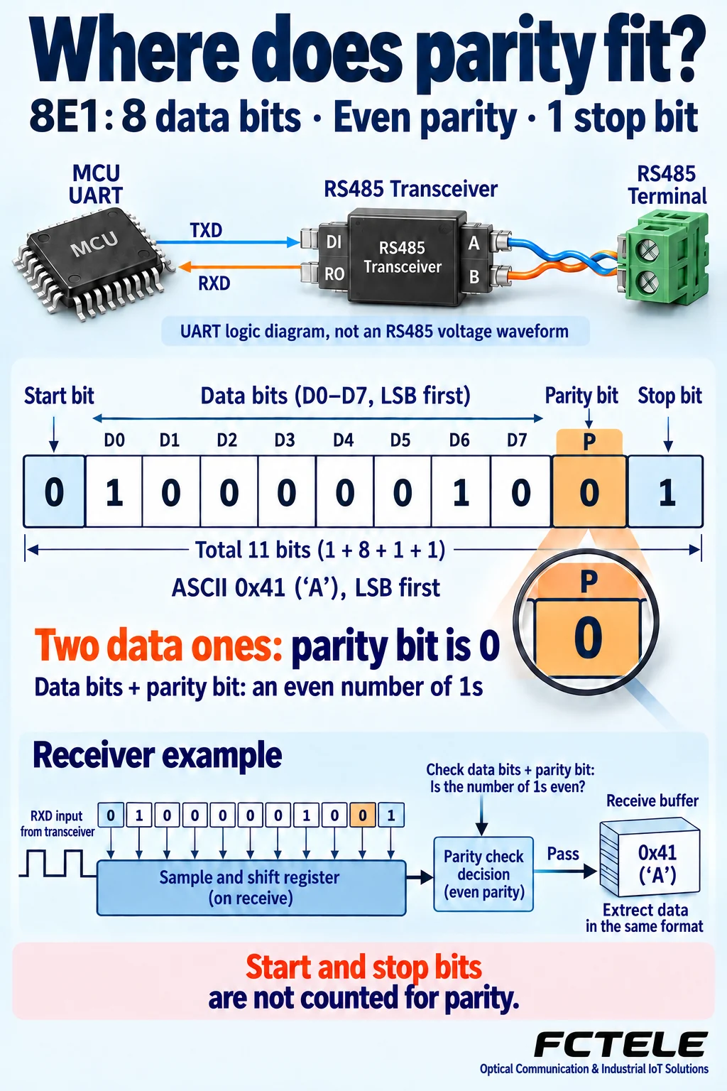
The check covers a character, not a complete application message
UART stands for universal asynchronous receiver/transmitter. It is commonly the part of a chip that turns bytes into a serial sequence of bits and reconstructs bytes from received bits. A software message describing an instrument reading may contain several bytes. The UART sends individual characters, adding start and stop bits to identify their boundaries and, when configured, a parity bit. An application message and a serial character are containers of different sizes.
RS232 and RS485 mainly define electrical interfaces for representing and carrying signals; parity belongs to the character format. Using RS485, or adding a fiber link between interfaces, does not automatically strengthen the check on character content. A link indicator or the arrival of bytes shows that a particular layer is doing something. It does not confirm the application content.
Also distinguish a character boundary from the beginning of an entire message. Recognizing the next start bit does not tell a UART which byte is an address or command. The higher-layer protocol normally defines the message boundary. Ignoring that distinction can lead an application to assemble individually valid characters into an incorrect message.
Even parity does not mean the parity bit is always zero
Even parity makes the total number of ones in the data bits and parity bit even. Odd parity makes that total odd. The receiver applies the same rule. A mismatch tells it that the character is suspect. The parity bit can therefore be either zero or one, depending on the data. Even does not mean a permanently zero bit, nor odd a permanently one bit.
Consider the character A, commonly represented by the hexadecimal byte 0x41. Its eight data bits contain two ones. In 8E1, 8 means eight data bits, E means even parity, and 1 means one stop bit. The two data ones are already an even count, so the parity bit is zero. A common UART sends the least significant bit first. The illustration is ordered D0 through D7; this is different from writing a binary number with its most significant bit on the left.
This count covers only the configured data bits and parity bit, excluding start and stop bits. A start bit announces the beginning of the character. A stop bit provides a format-checking opportunity at the end. These bits have separate jobs. Being next to one another on the same signal does not make them part of the same parity check.
With no parity, the additional parity bit is absent while the data bits are still transmitted. Suitability depends on the protocol and equipment design. A higher-layer check is not permission to change one endpoint’s character format arbitrarily. Both endpoints must first interpret the positions using the same agreement before their received content can be compared.
One flipped bit and two flipped bits produce different results
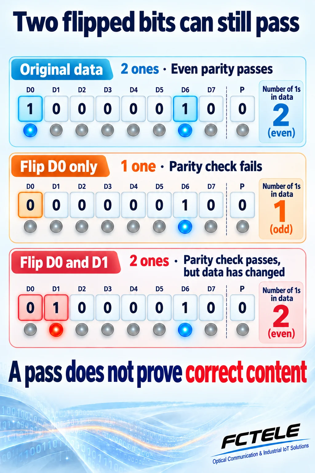
Continue with the same example. Suppose D0, originally one, is interpreted as zero while every other data bit and the parity bit stays unchanged. The receiver now counts one one. An even count has become odd, so the check detects a problem. This example concerns bits already interpreted by a receiver; it does not imply that real analog interference always creates a particular error pattern.
Now suppose D0 changes from one to zero and D1 changes from zero to one. The original count was two ones and the new count is still two. Even parity passes, although the byte has changed. The reason is simple: the check retained only whether the total was odd or even, not the answer at every position. Within a fixed character boundary, an odd number of flipped data or parity bits changes parity; an even number does not.
A pass therefore means that this rule did not detect a violation. It does not mean the received bits match the original. Parity cannot identify which bit was wrong, reconstruct the original byte or authenticate the sender. Missing or repeated bytes and an incorrect application-message sequence also require other evidence.
What happens after the equipment detects an error?
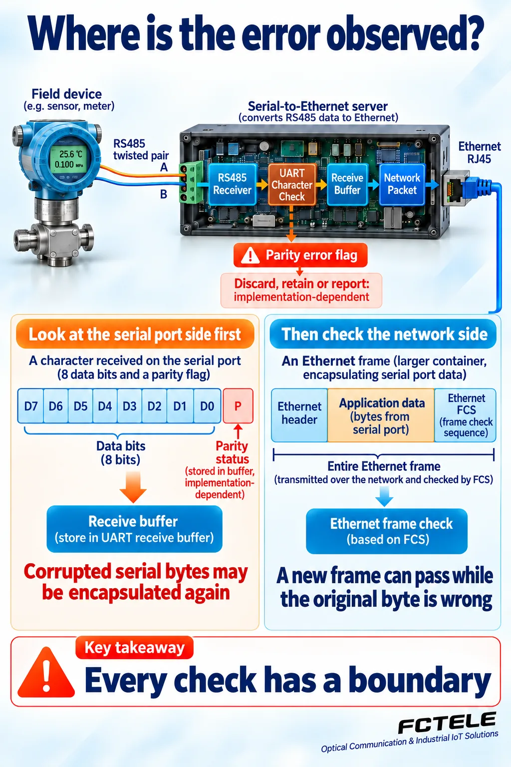
A receiver typically samples the input using its local timing, reconstructs the data bits, checks the character format and passes results toward a receive buffer and software. Some chips provide a parity-error flag with the received character. Whether an errored character enters the buffer, is discarded, increments a counter or triggers an alarm depends on the chip, driver and product firmware. UART does not specify one universal policy for all equipment.
Consequently, an absent error count does not immediately prove an error-free line. A product may not expose the counter, collection software may not retain the flag, or the observation point may already be downstream of error handling. Establish where each diagnostic comes from, which port it covers and whether a restart resets it. Then correlate its timing with the application problem.
A serial server introduces another checking boundary
A serial-to-Ethernet server may collect received bytes in a buffer and place them inside network packets. The network segment performs its own checks on the newly encapsulated data. If a corrupted serial byte has already been accepted as ordinary content, the network can deliver that content correctly. A clean network-frame record does not prove that the initial serial character was correct.
Conversely, downstream checking cannot reconstruct content already discarded upstream. The application must apply the length, sequence, check fields and timeout rules specified by its own protocol. CRC is an error-detection method, not encryption or identity authentication. The available fields and failure-handling rules depend on the actual protocol; one universal checklist cannot be assumed to exist inside every serial message.
Fix the format first, then gather evidence
Record the baud rate, data-bit count, parity mode and stop-bit count at both ends and at every intermediate device that terminates and retransmits characters. Having 9600 written at both ends is insufficient: 8E1 and 8N1 interpret the latter part of a character differently. Do not casually disable parity just to make characters appear. That can remove a warning without removing the cause.
Next, perform a controlled test with known content. Preserve the transmitted and received bytes, error flags and timestamps. When appropriate, observe a suitable logic-side signal. UART logic levels, RS232 voltages and an RS485 differential signal are different measurement points. Confirm instrument suitability, grounding and safe conditions before measuring. Comparing evidence on both sides is usually more useful than judging a terminal window solely by whether it displays garbled text.
Do not preserve only text displayed in a terminal window. Some bytes are not printable and a display program may replace them with spaces, question marks or nothing. Different character encodings can also render identical bytes differently. Preserve raw bytes in hexadecimal and identify the observation point to distinguish changed transport content from a different display interpretation.
Distinguish transport capability from checking capability
The Feichang website includes real products such as a 16-channel RS232/422/485 fiber modem. Such equipment illustrates how a serial path can be extended using fiber. Fiber transport does not itself guarantee the business content, and a product name does not prove support for a particular error counter, application-message check or error-correction feature. Confirm the character formats, supported rate range, error handling and diagnostic interface for the specific model before purchase and commissioning.
Keep three points in mind: agree on the format; a passed check means only that no violation detectable by that check was found; and trustworthy application data still require the message boundaries, validity states and application rules to be verified. This view preserves the value of parity without treating it as universal insurance.
If a diagnostic interface exposes only one total error count, establish whether it combines parity errors, invalid stop-bit framing and buffer overruns. Similar symptoms can have different causes. Separate the error types and compare ports, loading and timestamps before deciding to investigate format settings, the physical line or the speed at which software reads the buffer.
Sources
Texas Instruments: UART protocol and error overview explains character structure and synchronization. Microchip: USART Parity describes parity generation and error flags. Microchip: Serial Interfaces and Bus Error Management discusses error-detection limits. Product reference: Feichang 16-channel RS232/422/485 fiber modem (Chinese). Chip documentation supports generic explanations and does not establish which chip a Feichang product uses or that it supports every listed feature.
Translated from the Chinese technical article: Read the original Chinese article.
Common practical questions
Is the even-parity bit always zero?
No. Even parity makes the total number of ones in the data bits and parity bit even. The bit is zero when the data already contain an even number of ones, and one when they contain an odd number. Start and stop bits are outside this count.
Why can corrupted content still pass parity?
Parity preserves only whether the count is odd or even. Within a fixed character boundary, an even number of flipped data or parity bits leaves that property unchanged, so corruption can pass undetected. Parity cannot reconstruct the original byte. Apply the checks specified by the actual application protocol.
Can the serial server’s network checks replace parity?
No. The network checks newly encapsulated data. An already corrupted serial byte may be encapsulated correctly, while content discarded upstream cannot be recovered by a downstream check. Verify the character format, device error handling and application-message rules separately.
Scope and further reading
Generic parity examples and serial handling concepts, not measurements or guaranteed model-specific behavior.
