


4B/5B CODING, AT A GLANCE
Why rewrite four data bits as five code bits?
The physical receiver needs a recognizable signal and reliable timing. In 100BASE-TX and 100BASE-FX, a fixed mapping converts four data bits into five-bit code groups before later signal processing. Decoding restores the original content. The extra positions support the transmission representation; they do not create user bandwidth, encrypt a message or guarantee error correction. Other Ethernet standards can use different codes.
Map the data
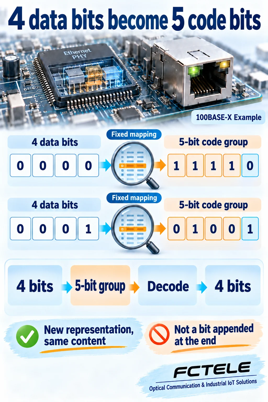
A fixed code table replaces each four-bit data group with five coded bits.
Recognize transitions
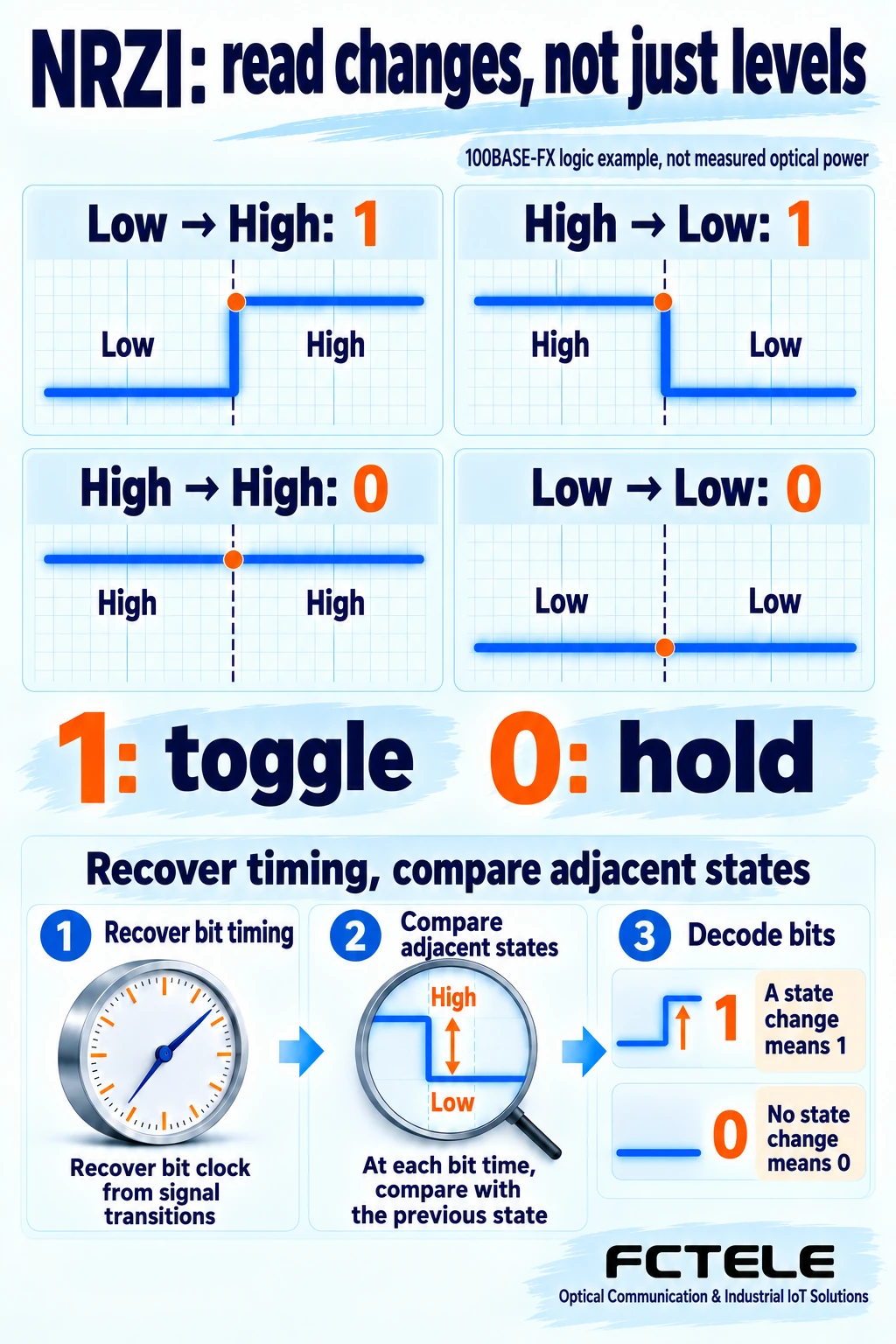
In this NRZI example, a one toggles the state and a zero preserves it.
Check the interface
A shared code does not make copper and optical interfaces physically interchangeable.
Identify the standard
Read the actual operating speed and whether the port is 100BASE-TX or 100BASE-FX.
Locate the observation
Distinguish decoded capture bytes from PHY diagnostics and physical signal measurements.
Confirm the model
Check official model documentation for supported interfaces and available error counters.
Selection and verification checklist — expand
| Check | What to confirm | How to verify |
|---|---|---|
| Physical standard | Actual speed and medium | Read port status and exact model documentation. |
| Code mapping | Data versus control groups | Consult the relevant standard or PHY documentation. |
| Signal representation | TX and FX later stages differ | Trace the documented transmitter and receiver functions. |
| Diagnostic scope | Counter meaning and direction | Read definitions and correlate timestamps with symptoms. |
| Performance scope | Data rate versus coded stream | State which layer each rate describes; do not promise application throughput. |
Conceptual diagrams, not measurements, wiring instructions or a particular product circuit.
A switch receives zeros and ones, so why change the way they are written before transmission? The physical receiver needs signals it can recognize and time correctly. In certain Fast Ethernet interfaces, 4B/5B coding maps four data bits to a five-bit code group. The message stays the same, but its representation on the link changes. Start with that distinction rather than treating coding as extra user bandwidth.
Separate message content from its representation
Handwriting and printed type can carry the same words while following different visual conventions. This analogy helps explain line coding: it changes how information is represented for transmission, rather than changing a business command into a different command. The analogy has a limit. Real interfaces must follow exactly the same coding rules; they cannot guess what a sender intended.
Inside Ethernet equipment, the MAC, or media access control function, handles frame-level tasks. The PHY is the physical-layer transceiver function: it sends data over the actual medium and recovers signals from it. This article focuses on 4B/5B in 100BASE-TX copper and 100BASE-FX fiber interfaces. It does not present this as the coding rule for every Ethernet port or speed.
The packet bytes displayed by ordinary capture software have generally already passed through receiver decoding. Not seeing five-bit code groups on screen therefore does not mean the port skipped coding. Your observation point is simply at another layer. Establish which stage a tool observes before comparing software bytes directly with physical signal states.
Why a receiver needs timing clues
The transmitter sends successive bits using its clock. The receiver must know when to decide the value of each bit. Knowing the approximate rate is not the same as receiving a separate announcement of every bit boundary. Device clocks differ slightly, and the channel affects the signal, so physical-layer circuitry recovers suitable sampling timing from the received signal.
If a direct representation produces a long stretch without transitions, the receiver has fewer opportunities to keep its timing aligned. The 4B/5B data mapping selects code groups suited to subsequent line representation, preventing ordinary data from producing arbitrarily long runs of zeros. It works with later coding stages. Merely adding one bit cannot by itself solve every synchronization, noise or attenuation problem.
This also explains why no new application message does not necessarily mean a motionless physical link. The physical layer must represent idle and the required start and end conditions. The receiver uses such states to maintain and recognize the link. An idle code group has physical-layer meaning; it is not a new application command delivered to the control program.
A fixed mapping, not a bit added at the end
Four data bits have sixteen possible combinations. An agreed mapping assigns a five-bit code group to each combination. For example, 0000 maps to 11110, while 0001 maps to 01001. After finding code-group boundaries, the receiver applies the reverse mapping to recover the original data. A lookup table explains the idea, but chip logic can implement it; a switch need not literally store a paper-like table.
A common misunderstanding is that the original four bits remain unchanged and a zero or one is appended. The two examples show why that is incorrect: the entire five-bit representation is selected. This is also different from UART parity, which calculates a check bit from the number of ones. The object being handled, the purpose and the location in the communication path are different.
Five-bit combinations can also represent control code groups rather than ordinary data. A receiver must distinguish data from defined control states instead of forcing every five-bit pattern into a four-bit value. Only two data examples are used here to explain the principle. Consult the applicable standard and chip documentation for complete control sequences and state-machine behavior.
Why a four-to-five mapping still belongs to 100 Mb/s Ethernet
The additional positions require the line side to carry more coded bits for the same amount of data. They do not create extra user data. In a typical 100BASE-X data path, a 100 Mb/s data stream corresponds to a 125 Mb/s coded-bit stream. That relationship explains coding overhead; it is not additional bandwidth available to an application.
File-transfer performance also depends on frame headers, interframe gaps, higher-layer protocols, packet sizes and equipment processing. The number 125 cannot directly promise an application transfer rate in bytes per second. Nor should the same coding overhead be subtracted again as a second mysterious loss. Specify whether a performance figure describes the data rate, coded-bit stream or useful application throughput.
Because the sender and receiver use complementary representations, decoding does not increase the number of original data bits. Think of a shared writing convention that makes transmission recognizable. It does not give a business message additional useful content when that message arrives.
NRZI reads changes rather than a high level alone
After 4B/5B produces code groups, later stages represent them as states suitable for the interface. In the NRZI rule used for 100BASE-FX, a one toggles the signal state and a zero preserves it. A one can therefore appear as a low-to-high or a high-to-low transition. The receiver looks for change, rather than deciding from one isolated high or low level.
The receiver recovers bit timing, compares adjacent states, interprets a transition as one and a hold as zero, then identifies code groups and recovers data. The high and low levels in the illustration are conceptual logic states. They are not measured optical power from a particular module, and they do not establish that the light must turn off for every data zero.
This rule has a defined scope. Other Ethernet rates and physical interfaces can use different coding and modulation. Applying one state diagram to every port merely because each device says Ethernet would misrepresent their actual operation.
Copper and fiber follow different later processing paths
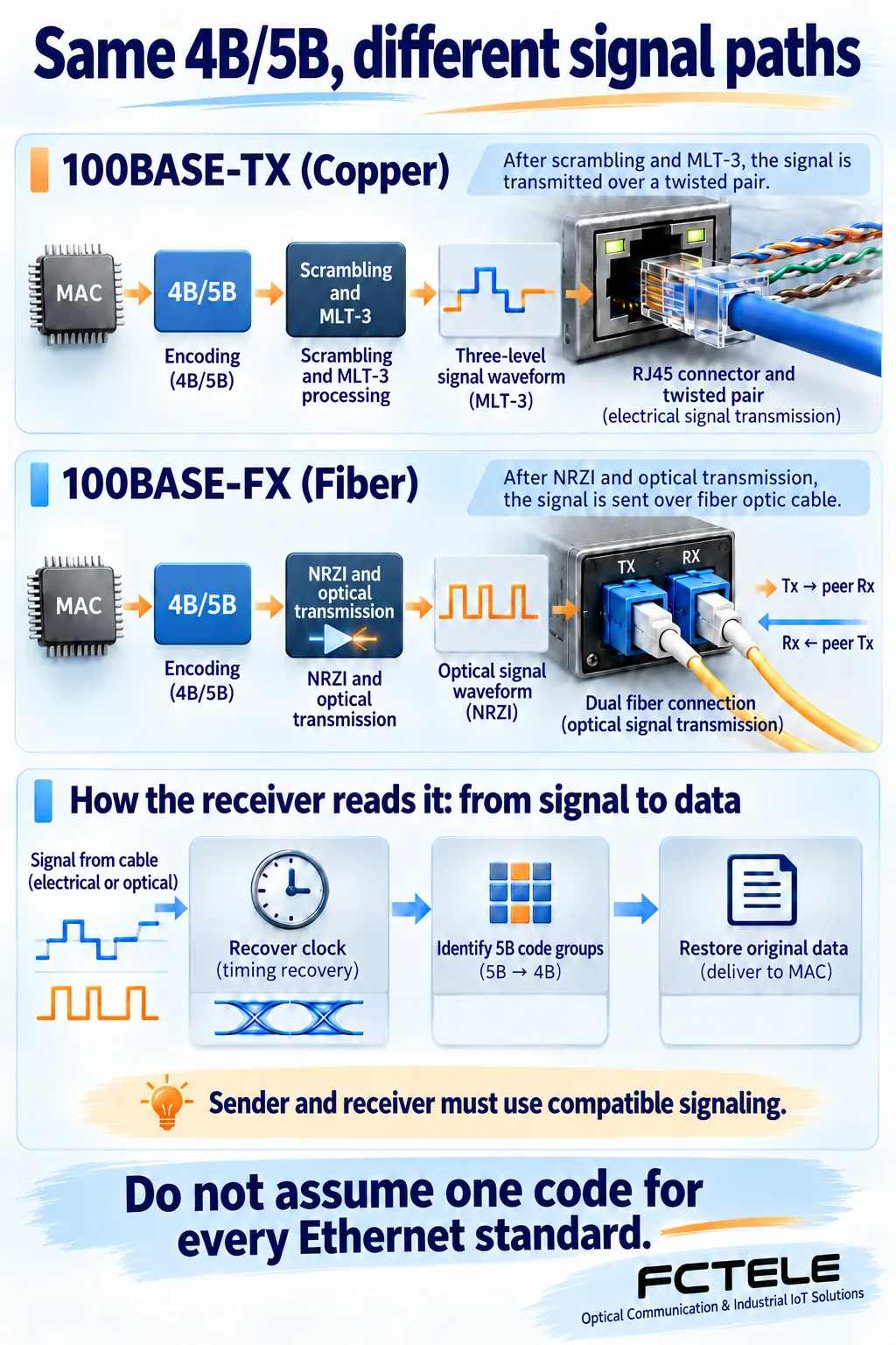
After 4B/5B, 100BASE-TX includes scrambling and MLT-3 processing. Scrambling uses a deterministic process to change signal characteristics, with complementary recovery at the receiver. It is not encryption for secrecy. MLT-3 uses multiple level states to form a signal suitable for twisted pair; three voltage levels should not be interpreted as three separate application digits.
The 100BASE-FX transmit path instead uses NRZI and optical transmission functions suited to the fiber interface. Sharing part of the coding approach does not make an RJ45 port directly connectable to fiber, or reduce media conversion to replacing a wire with glass. A real converter must handle the interfaces and their electrical or optical transmit and receive processes.
In the receive direction, the equipment also recovers timing, recognizes code-group boundaries, reverses coding and returns data toward the MAC. The stages in the illustration simplify their functional relationship. They are not the internal circuit of a particular Feichang product and do not enumerate every implementation detail.
How this helps in an industrial network
The Feichang website lists real products such as a miniature DIN-rail five-port Fast Ethernet switch, showing that 100 Mb/s copper ports remain an actual industrial interface category. This product reference supports the context, not an inference about its PHY chip. It does not establish support for code-group error counters, special diagnostics or optical ports. Confirm capabilities in the exact model documentation.
When troubleshooting, establish the actual operating speed and physical standard before correlating link status, receive errors and application symptoms in time. If coding-related counters are available, verify their definitions, direction and reset conditions. A normal ordinary packet capture cannot independently prove that every physical-layer stage is error-free. Conversely, one changed counter cannot by itself identify a damaged cable, fiber or chip.
The useful distinction is simple: coding gives content a representation both ends can recognize; receiving recovers that content; checks examine it within their own scope. Coding is neither encryption nor error correction. Keeping these jobs separate helps you read manuals, interpret diagnostics and choose an evidence-based next check.
Sources
Texas Instruments DP83849I data sheet: code-group mapping and 100BASE-TX functions. Texas Instruments DP83822 data sheet: 100BASE-FX transmission and reception. Microchip Ethernet Overview: interface categories. Product reference: Feichang miniature DIN-rail five-port Fast Ethernet switch (Chinese). Chip documentation verifies generic mechanisms. It does not establish that this product uses those chips or supports all their features.
Translated from the Chinese technical article: Read the original Chinese article.
Common practical questions
Does 4B/5B append a parity bit to the original four bits?
No. A fixed table maps the whole four-bit combination to a five-bit code group, for example 0000 to 11110. The receiver decodes it in reverse. This serves a different purpose from parity and does not guarantee detection of every error.
Why is the port still 100 Mb/s when it uses five-bit groups?
The 100 Mb/s figure describes the data side. A typical 100BASE-X encoded bit stream runs at 125 Mb/s. The extra positions serve the line representation, not additional application bandwidth. Frame and upper-layer overhead also affect application throughput.
Do all industrial switches use the same line coding?
No. Coding depends on the physical standard and rate. 100BASE-TX and 100BASE-FX share 4B/5B mapping but use different later electrical or optical processing. Other Ethernet interfaces can use other methods.
Scope and further reading
Generic 100BASE-TX and 100BASE-FX coding examples, not measurements or a particular product circuit. Other Ethernet standards can use different coding.
Related CRC and FCS guide · Related preamble and frame-gap guide
