

RS232 / SUPPLY CONVERSION
Where does the negative rail come from?
A flying capacitor first stores charge and then changes its reference connection. One terminal can move below ground while the terminal-to-terminal voltage initially remains unchanged. Controlled transfers replenish an output reservoir. This ideal inverting stage explains the mechanism; a real RS232 transceiver may also boost and regulate its supplies. Rail voltage alone does not prove communication performance.
01 · Charge
Connect one capacitor terminal to the input and the other to ground.
02 · Shift reference
Ground the first terminal. The second moves below ground in the ideal model.
03 · Transfer charge
Controlled switching replenishes the negative output reservoir.
Identify the rails
Use the exact chip documentation to distinguish supply pins from data pins.
Keep a known reference
Record the approved reference point, load and probe connection together.
Correlate the result
Compare supply changes with line waveforms and matching send–receive logs.
Selection and verification checklist — expand
| Check | Confirm | Evidence |
|---|---|---|
| Device | Supply and required capacitors | Exact chip and system documentation |
| Measurement | Approved reference and load | Rail and waveform records |
| Communication | Actual transmitted characters | Matching send and receive logs |
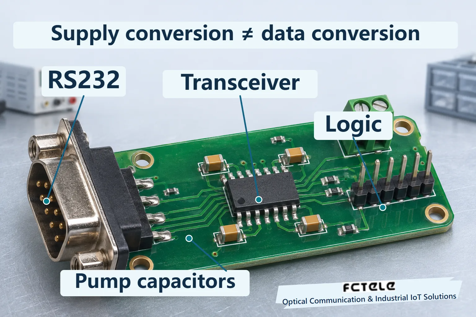
A serial board may have only one positive supply while its RS232 transmitter produces positive and negative voltages relative to signal ground. UART software does not create the negative rail. Some RS232 transceivers integrate a charge pump that stores charge in capacitors and switches their connections to establish supplies for the line drivers. Understanding it starts with separating power conversion from data transmission.
Power and data follow different paths
The UART organizes serial characters into digital logic. Its board-level signal and an RS232 line are different electrical interfaces. A transmitter accepts the logic state and uses its supplies to drive the external line. A receiver converts the incoming line state back to internal logic. The charge pump establishes power conditions. It does not select a baud rate, parity, stop bits or message length.
A negative voltage is always relative to a reference. If signal ground is zero and a node is 3 V below it, that node is −3 V. It still has an electrical potential. Establish the meter reference before measuring, and do not interchange chassis, protective earth and unknown signal references. In an isolated system, follow the reference arrangement on each side rather than bypassing the barrier to create an arbitrary common ground.
External capacitors are common around integrated charge-pump transceivers, but their number, value, rating and connections depend on the device. A flying capacitor changes its connections between phases. A reservoir capacitor helps maintain an output rail while the load draws charge. Similar-looking parts are not automatically interchangeable. The illustration separates connector, transceiver and capacitor cluster on a generic board, rather than showing a Feichang teardown.
Charge the capacitor and track the voltage across it
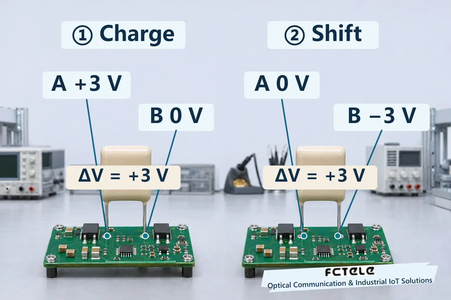
Consider one ideal inverting stage, leaving the boost and regulation of a complete RS232 device aside. Assume a +3 V input relative to ground and call the flying capacitor terminals A and B. In the first phase the terminal A connects to +3 V and terminal B to ground. After charging, the terminal A is about 3 V above terminal B. The useful quantity is this difference, rather than a requirement that either terminal remain permanently grounded.
A capacitor temporarily stores charge. It is not an unlimited battery, and its voltage changes as charge is taken from it. Real switches and components introduce losses, and charging is not instantaneous. The first phase needs the intended switch configuration and time, with the achieved result dependent on the device and operating conditions.
No new serial data is created by this step. Internal oscillation and switch control repeat the power-conversion sequence. Their frequency is not the UART baud rate. A quiet serial interface does not prove that the pump has stopped. Shutdown, automatic power saving and rail retention depend on the device and equipment design.
Move the reference and the other terminal goes below zero
In the second phase the relevant first-phase connections open before the terminal A is connected to ground. In the ideal model, the capacitor voltage cannot change arbitrarily at the instant of switching. Its terminal A remains 3 V above its terminal B. With the terminal A now at zero, terminal B is about −3 V. Appropriate switching transfers charge to a negative reservoir capacitor, and repeated cycles establish the negative supply.
Check the two sets of node values. During charging, A is +3 and B is zero. During transfer, A is zero and B is −3. A minus B remains +3 in both cases. Their positions relative to ground change. The illustration preserves the capacitor orientation and changes node values. It does not instruct a user to reverse a physical capacitor or attach an RS232 signal directly to an external rail.
This illustrates an ideal inverter only. It does not establish that a −3 V stage can drive a complete RS232 interface. A transceiver can boost first and then invert, or use other stage counts and controls to supply the specified load. Supply-rail voltage also differs from the transmitter’s actual loaded line swing. Check the chip, supply range, load and output requirements together.
The switch phases must occur in the intended order. Treating every pictured connection as simultaneously closed produces a different circuit and can create a short. The two phases therefore appear separately, with detailed switch numbering and protection omitted. This is an explanation of charge transfer, rather than a construction drawing or a universal internal layout.
Why the negative voltage can move toward zero under load
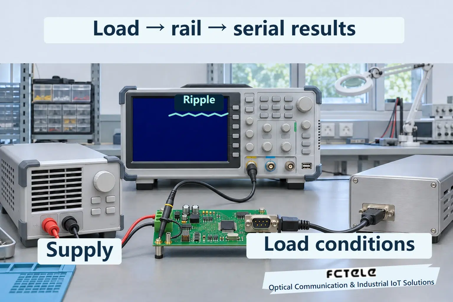
The reservoir capacitor supplies charge between pump transfers as the line driver and other circuits consume it. Its voltage changes until a subsequent cycle replenishes it, producing ripple. Switch losses, effective capacitance and operating frequency also influence the average rail. A higher load can move the negative voltage closer to zero. An unloaded reading does not guarantee the result at every data rate and cable condition.
Cable capacitance must be charged and discharged as the signal changes, altering the driver load. Correct-looking UART characters therefore do not establish the quality of the line-side voltage or received result. Conversely, a healthy negative rail does not prove that the pinout, directions, reference connection and protocol settings are correct.
Follow the specified capacitor type, capacitance, voltage rating and placement rather than increasing capacitance indiscriminately. Startup and steady-state requirements matter. Do not open equipment to reach undocumented test points for the purpose of this explanation. Record supply and interface conditions and use the manufacturer’s permitted comparison method.
Relate power evidence to communication evidence
On an authorized bench, where the interface documentation permits internal measurements, establish supply and reference conditions first. Record positive and negative rails, load and line output separately. For ripple observations, retain probe connection, coupling and timebase. A meter average does not describe the entire waveform. Send identifiable characters and correlate errors with power behavior instead of diagnosing a charge-pump fault from garbled text alone.
Feichang’s DIN-rail terminal with one RS485 and one RS232 channel is a real serial application example. Its supply, internal chip and maintenance procedure require delivered documentation. This article does not identify its charge pump or transfer a third-party chip’s voltages and capacitors to the equipment specifications. Optical transport extends the service, while each end retains its own serial supply and electrical interface requirements.
Preserve both electrical measurements and the communication setup: models, serial format, cable and request-response records. Establish a short-link baseline before restoring the installed path in stages. A negative rail comes from timed charge transfer. Reliable communication requires the whole signal path to remain within its operating conditions.
Sources and scope
TI — charge-pump operating phases · TI SLCA001A — designing with the TRS3122E · Feichang RS485 and RS232 fiber terminal (Chinese)
Translated from the Chinese technical article: Read the original Chinese article.
Common questions
How can one positive supply create a negative voltage?
Charge a flying capacitor, switch its reference connection, and transfer charge to an output reservoir. Actual chips may also boost and regulate their rails.
Is the illustrated −3 V an RS232 product specification?
No. It only checks the node relationships in an ideal inverting stage, not a complete driver requirement or product rating.
Does a healthy negative rail prove the serial link works?
No. Check the loaded line output, reference, wiring, serial settings and actual communication results as well.
Further reading
UART logic levels and electrical interface conversion · How RS232-to-RS485 conversion preserves characters
