


First, decide whether you need to know a state or a value
Whether a door is closed only requires knowing two states; how high the water level in a tank is requires knowing a continuously changing value. The former usually uses discrete I/O, and the latter usually uses analog signals. A discrete I/O optical transceiver extends the corresponding states, and an analog optical transceiver extends the matching current or voltage measurement. They can appear in the same project at the same time, but they cannot replace each other just because both connect to terminals and fiber.
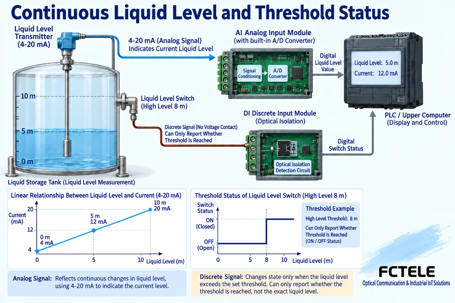
For example, the opening and closing of a door magnetic contact is sent to the alarm input in the control room, and the 4–20mA from a liquid level transmitter is sent to the PLC analog input. A high liquid level alarm can also be reported by another switch contact, but that contact only indicates whether the threshold has been crossed and cannot tell you the complete liquid level. Before selecting a model, clearly write down what the original signal is and what information is needed at the far end. This can avoid mistakenly purchasing a measurement requirement as alarm state transmission.
Where do DI, DO, AI, and AO each sit?
DI means digital or discrete input, and DO means the corresponding output; AI means analog input, and AO means analog output. Inputs usually obtain information from field signals, while outputs provide matching signals to remote receiving equipment. The same multi-service device may have these interfaces at the same time, but the actual quantity, direction, and combination still need to be confirmed by model. The number of interfaces cannot simply be treated as the number of bidirectional channels.
The measurement path from the sensor to the PLC can be represented as field AI to remote AO, then connected to the PLC AI. When the PLC sends a current setpoint down to a field actuator, the direction is reversed, and whether this return path can be provided at the same time must be confirmed separately. When marking the sending end and receiving end, the specific service direction should be used as the basis, to avoid always calling the entire device a transmitter and missing the channel in the other direction.
Discrete I/O also requires checking the electrical form
A dry contact itself does not actively provide the corresponding detection voltage, such as one set of contacts in a relay; a wet contact usually involves an external voltage signal in the interface conditions. Whether the device input detects a contact, which voltage, or how the common terminal is connected must be checked in the actual instructions. Do not connect an external power supply to a terminal that only allows dry contacts, and do not treat an ordinary set of relay contacts as capable of carrying any voltage and current.
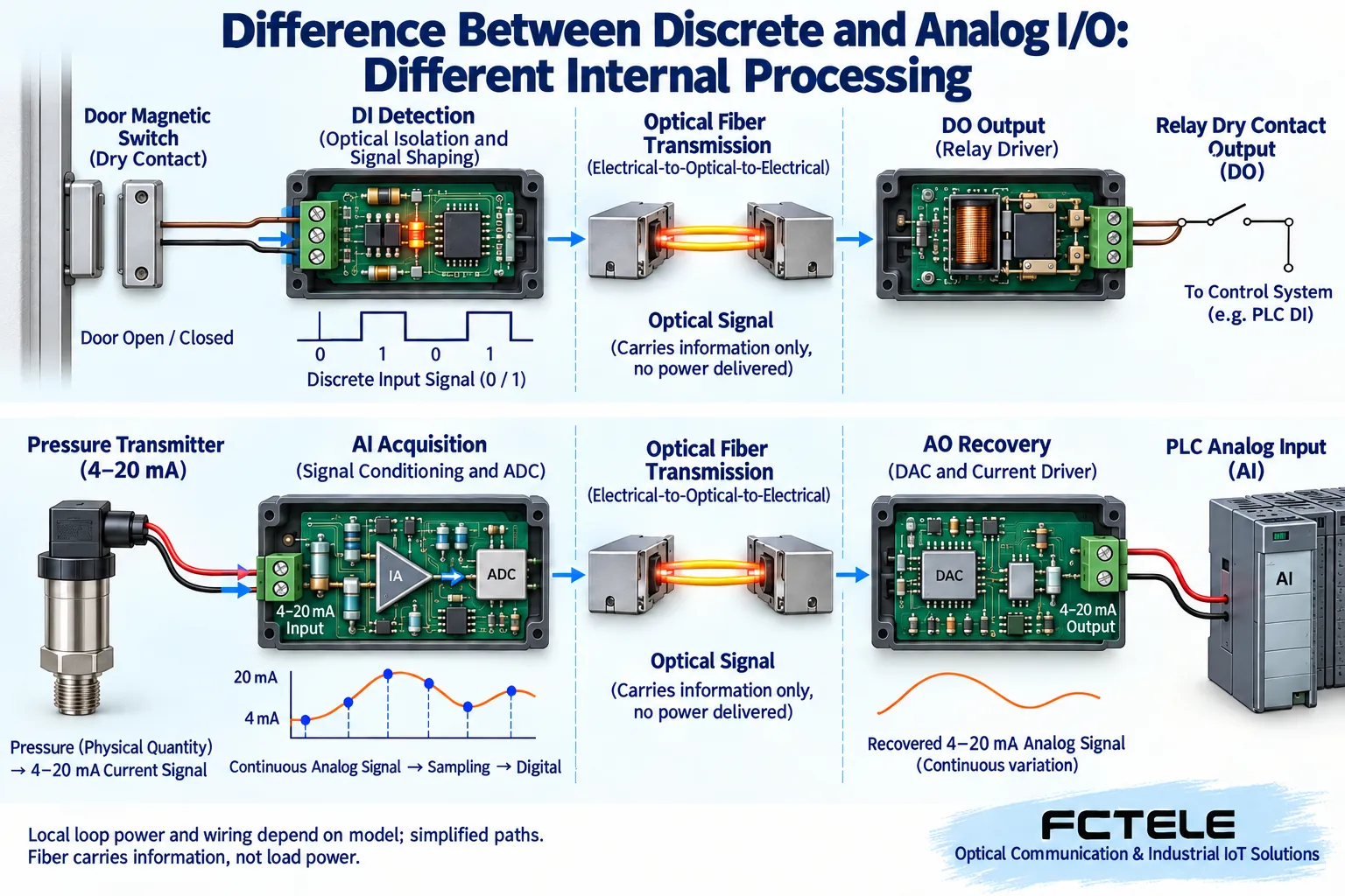
The input detection circuit turns the physical state into corresponding logic information, and the receiving end then outputs it as a relay, electronic switch, or specified level. DO is not necessarily a mechanical relay, and the correspondence between input state and output opening/closing also needs to be tested. Relay response, contact bounce, and the device input filtering will affect fast pulses. An ordinary alarm channel cannot automatically take on any high-speed counting or encoder task.
Analog signals requires continuous values and conversion accuracy
An analog input first goes through conditioning, then the ADC converts current or voltage into a digital code; after transmission over the optical link, the receiving end can use a DAC to restore the corresponding analog output. ADC and DAC are analog-to-digital and digital-to-analog converters, respectively. The signal is no longer just on or off; range, resolution, offset, and gain error all affect the final measurement.
4–20mA and 0–10V cannot be connected to each other based on terminal appearance alone. A current loop requires checking the power supply role and load conditions, and a voltage signal requires checking the input range, impedance, and reference terminal. A continuous signals cannot simply be drawn as a switch, and it cannot be claimed that all conversion errors disappear after passing through fiber. Fiber improves the transmission medium conditions, but the analog interfaces before and after still need independent matching and verification.
A clear example can reveal a range error
Assume the liquid level range is 0 to 10 meters, and the transmitter represents the liquid level linearly with 4–20mA. Then 4mA corresponds to 0 meters, 12mA corresponds to 5 meters, and 20mA corresponds to 10 meters. Even if the far end correctly restores 12mA, if the PLC is incorrectly set to 0–20mA corresponding to 0 to 10 meters, the display will become 6 meters. This is a scaling definition error, and replacing it with a longer fiber or more ADC bits cannot solve it.
The door magnetic contact example is different: open and close it repeatedly to confirm that the remote state and alarm logic match the site, and also check what state it shows when the wire is broken. Usually, an ordinary contact wire alone cannot automatically distinguish between a normal open circuit and a broken cable; if line supervision is required, a system with the corresponding circuit or supporting mechanism should be selected. Both continuous values and states must be accepted, but the test methods cannot be exactly the same.
Multiple signals do not necessarily each occupy one fiber
A hybrid device can organize multiple states and measurement codes into the transmission structure it supports, and restore them at the matching receiving end. Therefore, how many signals one optical link can carry depends on the device implementation. It cannot be said that each analog channel must occupy one fiber core. The number of optical ports, the number of physical fiber cores, the service direction, and the number of channels are four different questions.
When bidirectional transmission or backup is required, the corresponding optical modules and port relationships should be checked. Single-fiber bidirectional and two backup paths are not the same concept; the former describes the way bidirectional services are carried on one fiber core, while the latter involves how to switch during a fault. Without model evidence, do not add ring network or redundancy capabilities out of thin air to a single-channel product just to draw a nice-looking topology.
Check hybrid optical transceivers and network collectors separately
The Feichang Technology hybrid optical transceiver details introduce optional combinations of analog signals, discrete I/O, and serial ports, which can be used to check multi-service requirements on the same optical link. The page lists different discrete I/O output forms, indicating that the contact or electronic output version must also be confirmed during procurement, and it is not enough to just fill in one DO. Channel combinations and port power should be based on the terminal table of the exact model.
The Feichang Technology DI/DO/AI/AO fiber optic collector documentation lists acquisition methods such as Modbus RTU and TCP. When network register access is required, the station number, address mapping, data type, and update mechanism must all be checked at the same time, not just the physical optical port. Paired restoration of analog output and reading values over the network are different delivery paths, and protocol acquisition does not automatically mean providing AO of the same range for all field terminals.
Fill in the acceptance table separately for each type of signal
For discrete I/O, record the input electrical conditions, open/close states, remote output form, and load, and test open/close, power-up, and loss-of-contact states channel by channel. For analog signals, record the input and output ranges, power supply, load, and PLC scaling, and use low, middle, high, and intermediate points to verify values; when fast response is required, separately test update and step response. Hybrid devices should also test the channel combinations that need to run at the same time.
Installation and testing should follow the terminal instructions and on-site maintenance conditions, and analog output must not directly replace actuator control that has not been checked. Save the channel mapping to ensure the door magnetic contact is connected to the door magnetic variable and the liquid level is connected to the liquid level variable. Choose the right discrete and continuous information, then separately prove the electrical interface, optical link, and remote reading, so that a set of equipment can be used for the task that is truly needed.
Documentation note: The principle diagrams have been checked against technical content and are used to explain general mechanisms. They are not actual product photos or measured records. Specific interfaces, modes, and capabilities are subject to the selected model, version, and on-site verification.
Verification materials: Feichang Technology analog product category
Feichang Technology hybrid optical transceiver details and fiber-break hold description
Feichang Technology DI/DO/AI/AO fiber optic collector details
TI: Two-wire 4–20mA loop and voltage headroom
Related technical topics: How to choose an analog optical transceiver: range, accuracy, refresh cycle, and optical path acceptance How FPGA analog-to-fiber works: channel scheduling, refresh cycle, and loss-of-contact output How analog optical transceivers connect to industrial monitoring: PLC range, bidirectional channels, and loss-of-contact strategy How to troubleshoot an analog optical transceiver: no reading, deviation, jumping, and fiber-break hold How an analog optical transceiver transmits signals: current/voltage, ADC/DAC, and remote output Can a data optical transceiver do interface and protocol conversion? Boundaries of serial ports, analog signals, and Ethernet acquisition How analog video optical transceivers differ from analog signals optical transceivers: modulation, sampling, and measurement
Translated from the Chinese technical article. Source first published: 2023-11-22. Source last revised: 2026-10-13T12:13:11+08:00. Read the Chinese source
