


First draw the power path, then decide which plan to use
Surveillance cameras need both to transmit images and to receive electrical power. A local power supply provides matching power near the camera. A centralized DC power supply sends power to multiple points through distribution branches. Standard PoE transmits data and power simultaneously over compatible Ethernet cables. The three methods can be combined by area. You cannot give one best connection method for all projects based only on the number of cameras.
First list each point’s interface, allowed input, maximum power, distance, environment, and maintainable location. Then draw the data cable from the camera to the switch and the energy path from the power supply to the camera. Analog cameras and IP cameras may have different service interfaces. Only devices with the corresponding standard PoE powered-device capability can be connected using the corresponding PoE scheme. You cannot infer compatibility just because the network port or housing looks the same.
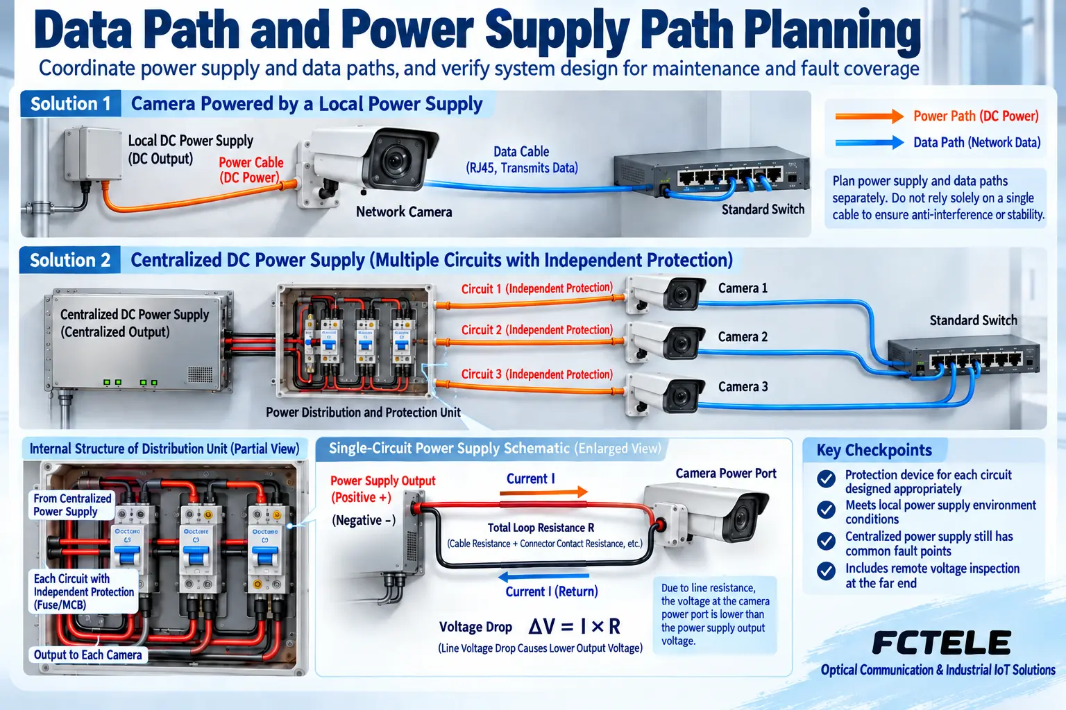
Local power is easy to divide into areas, but still check for a shared power source
A local scheme usually lets each point use a matching adapter or on-site power supply, while data runs on a suitable separate line. A failure of one local power supply mainly affects the load it serves, and the replacement location is also fairly clear. But if all power supplies come from the same upstream distribution branch, losing that branch can still affect all points. Multiple adapters are not sufficient proof of power independence.
On site, protect power supplies, connectors, and wiring from moisture, heat buildup, and mechanical pulling. A device marked outdoor does not mean its included adapter is also suitable for rain. Check the input form, polarity, rated capability, and the camera’s allowed conditions. Do not attempt to connect unknown interfaces. On-site mains power and protective earthing should be handled by personnel with the appropriate qualifications according to the project documents.
Why centralized DC power requires calculating round-trip voltage drop
A centralized power supply sends power to each camera through distribution and protection branches. This makes it easy to view and maintain in one place, but it also introduces a shared node. Lines are not ideal conductors. Current through the outgoing and return conductors and connections produces voltage drop. The camera receives the voltage at the load end. You cannot declare the remote power qualified just by measuring the central power supply’s no-load output.
According to the resistance model, voltage drop is approximately equal to current times total loop resistance. A pure calculation example: when loop resistance is two ohms and current is zero point five amperes, the voltage drop is about one volt. As current increases, voltage drop also increases. The loop here includes both the outgoing and return segments and the related connections, not just the one-way length. The example does not specify actual wire gauge, output voltage, or acceptance threshold.
Therefore, fixing a certain DC voltage, a certain cable, and a uniform one-hundred-meter limit in older articles cannot be used as a universal scheme. Calculate according to the camera’s minimum allowed input, startup and changing loads, cable and connection conditions, and then measure under load. Do not raise the power supply output without authorization to make up for voltage drop, causing overvoltage at near-end devices. Each branch’s protection and distribution capability must also match the actual design.
Standard PoE identifies first, then provides controlled power
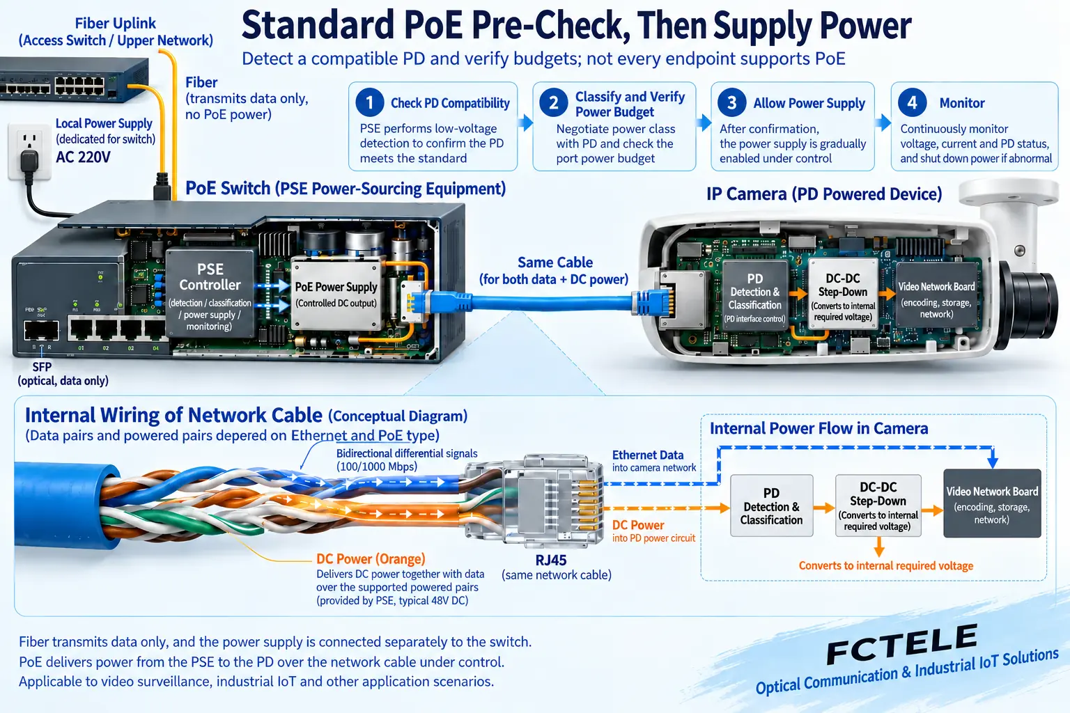
In standard PoE, the power sourcing equipment is called PSE, and the powered device is called PD. A compatible power sourcing end uses detection and applicable classification, budgeting, and other processes to decide whether to allow power, then continuously monitors the connection and load. The network cable carries both data and power, but inside the camera the network data is sent separately to the processing circuit, and power is sent to the powered and power conversion circuits.
Different PoE types and classes correspond to different capabilities. You cannot reuse the old conclusion that all devices are at most thirty watts. Check the PSE supported standard, PD requirements, available port power, and total device budget. Passive forced power or non-standard devices cannot use standard detection and protection conclusions. Even less should you directly add power to an unknown ordinary network port to test whether a camera is compatible.
Single-port, total device, and power input must all be sufficient
One port supporting the power required by a camera does not mean the total budget is sufficient when multiple ports work at the same time. The power sourcing end also has its own losses, cable losses, and upstream power supply limits. Related specifications may use different bases such as PSE output or PD available power. Before comparing, state the measurement location. Do not directly equate numbers from both sides, and do not double-count the same margin.
Infrared illumination, heating, pan-tilt movement, and startup may change the load. Planning should be based on the operating conditions and maximum demand supported by the specific camera. You cannot simply add up daytime stable power consumption. Power arrangement is not safer just by being larger. It must also meet port standards and allowed input. A PoE switch connected to a mismatched power supply may still transmit data but fail to provide stable power.
How to retrofit an existing ordinary switch
When a camera supports standard PoE but the switch does not, you can evaluate a matching PoE injector, also called midspan, to organize ordinary Ethernet data and its power capability to the corresponding output. When the camera has no PoE powered interface, only a verified splitter can separate PoE into network and matching DC output. Voltage, polarity, plug, and continuous load all need confirmation.
An injector and splitter are not guaranteed to work just by connecting any two small boxes. Additional devices add connections, space, and maintenance items. You need to verify data rate, power standard, and output. For points that already have a suitable power supply, keeping independent power may be more direct. Do not force conversion devices onto all old cameras just to unify appearance.
Fiber to the remote end, power still solved at the remote end
Across buildings or over longer distances, fiber can carry Ethernet service to a remote switch, which then connects to cameras through remote copper cables. Ordinary fiber does not carry central PoE power over, so the remote switch and cameras still need suitable power. Data redundancy and power continuity are also designed separately. Ring network communication recovery does not guarantee that remote power continues during a power loss.
The Feichang Technology model 3243 mini managed industrial switch details list four gigabit electrical ports, two gigabit optical ports, and PoE optional. It can be used to check this optical uplink plus near-end access scheme. Whether power is provided depends on the ordered version and input power conditions. Optical port, power, and PoE power fields should be confirmed according to the delivered manual. You cannot assume all versions support them just because of images from the same series.
Compare failure scope and maintenance cost at the same time
A failure in a centralized power supply, PoE switch, or shared uplink may affect multiple cameras at the same time. Local power may also have a shared distribution node. UPS can be designed as appropriate to extend power for some devices, but capacity, load, and downstream distribution are still limited. You cannot claim it will never be interrupted just because there is a UPS. Total cost also includes cables, protection, cabinets, spare parts, and downtime maintenance.
Selection should divide areas according to the allowed scope of impact. Record which power supplies, branches, switching nodes, and lines will fail at the same time. Suppose two separate workshops each have stable power. Camera power can be completed in each area and connected to the center by fiber. If unified maintenance is more important, evaluate centralized distribution and necessary backup. These are scheme analysis examples, not delivered customer cases.
Acceptance must cover nighttime and recovery processes
First use a small number of devices to establish a power and network baseline. Check actual input, PoE allocation status, and images, then add concurrent points. Test changing loads such as nighttime illumination according to the model’s allowed conditions. Save port, power, error statistics, and video playback results. Having images during the day does not prove that all devices start normally at night at the same time. A successful ping does not prove that power and recording are stable.
Arrange interruption and recovery in an isolated environment or an approved maintenance window. Observe power loss, network disconnection, and application reconnection separately. Keep recovery time and abnormal records. Deliver the power list, branch table, device configuration, and test conditions so maintenance personnel can distinguish camera failure, branch voltage drop, insufficient budget, or network problems, and recheck against the same baseline.
Documentation note: The principle diagrams have been checked for technical content and are used to explain general mechanisms. They are not product photos or measured records. Specific interfaces, modes, and capabilities are subject to the selected model, version, and on-site verification.
Verification materials: Axis camera typical and maximum power consumption description
TI standard PoE detection, classification, and startup process
TI PoE powered device power measurement
Feichang Technology mini four-electrical two-optical managed industrial switch
Feichang Technology industrial switch categories
Related technical topics:
Translated from the Chinese technical article. Source first published: 2020-04-28. Source last revised: 2026-10-13T02:31:06+08:00. Read the Chinese source
