


E1 is a bearer interface, not a video format
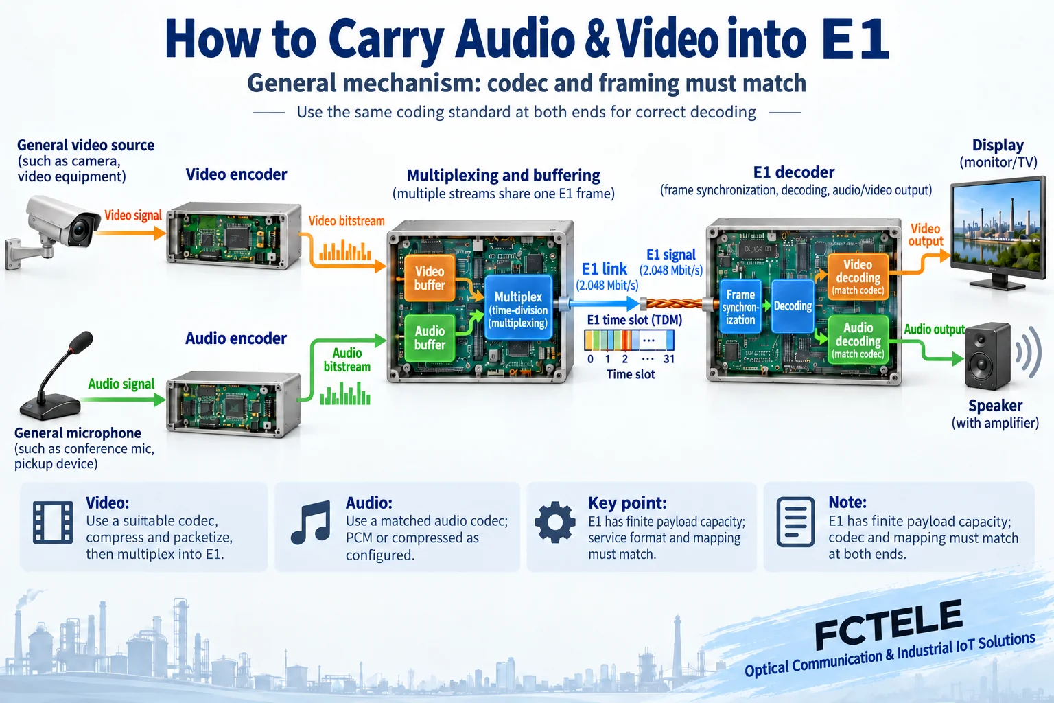
An E1 video and audio solution organizes supported video and audio encoded data into an E1 channel, then restores the service at the other end according to matching rules. E1 itself does not understand pictures, and it will not automatically turn any camera into playable video. You must confirm the service interface, encoding and decoding rules, framing method, clocking and bearer path at the same time. You cannot declare compatibility just because both ends have E1 connectors.
Older drafts jumped from stereo audio products to video, serial port and Ethernet functions, which easily mixes different product capabilities together. This article first explains the general video and audio bearer mechanism, then uses the company’s already clarified E1 audio model to explain the actual boundary. Parts without valid video model information are not written as functions already delivered by Feichang Technology or as fixed performance promises.
Why encode before organizing transmission
Analog sound goes through input conditioning, sampling and quantization to become a digital sequence. Video also needs appropriate sampling or reading of digital input, and uses an encoding method supported by the device. Sampling describes how the signal is obtained, while compression describes how the transmitted data is reduced. The two cannot be confused. The far end must support the corresponding encoding to restore the received data into usable sound or pictures.
The video and audio encoding output must comply with the effective capacity of the channel. Uncompressed high-definition video usually cannot be directly stuffed into one E1. It requires matching encoding and capacity design, and there may be trade-offs among picture quality, frame rate and latency. You cannot infer unlimited resolution, lossless compression or zero delay from the fact that the link can carry digital data. The data rate arrangement should be based on the actual service format and device manual.
How line rate and service capacity are distinguished
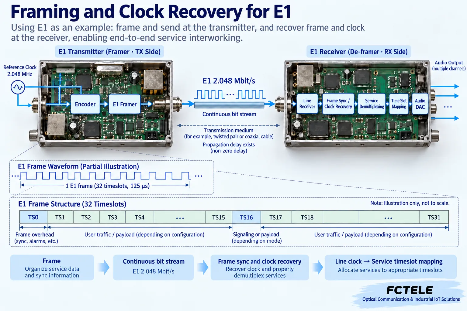
The E1 line rate is 2.048 Mbit/s. With a common framing method, a frame has 32 eight-bit time slots, and the frame repetition matches the line rate. Some positions carry overhead such as frame synchronization, and the specific service organization also depends on the device mode. You cannot directly treat the entire line rate as the upper limit of the application payload bitstream, and you cannot treat every E1 as a thirty-channel telephone structure.
General voice calculation example: two channels, 48,000 samples per second, sixteen bits per sample, the uncompressed sample rate is 1,536,000 bits per second. This is only an arithmetic example, not an FCA model parameter, and it does not include framing and additional overhead. Before adding video or auxiliary services, the total must be checked again. You cannot assume that because there are still empty sockets, there must still be transmission resources.
How multiplexing keeps services corresponding
Multiplexing arranges a transmission position or corresponding internal structure for each service, and far-end demultiplexing retrieves the content according to the same rules. The audio left and right channels should be restored to the corresponding outputs, video data should enter the matching video decoder, and auxiliary control should also return to the corresponding interface. Multiplexing is not directly twisting several wires onto the E1 line, and the internal mapping is not universal across all manufacturers.
The framing receiving end identifies boundaries through the specified structure, so it can continuously obtain the correct services. If the two ends match electrically on the line but have different internal mappings, there may be a normal signal but no correct sound or picture. Therefore acceptance should record the models at both ends, working mode, service allocation and framing settings, not just that the E1 indicator light is on.
Why clocking affects continuous playback
E1 transmits bits at a continuous rhythm. The receiving end needs to recover the line-rate beat and synchronize according to the corresponding structure. Video and audio output also depends on stable data supply and playback rhythm. If the clock relationship between the two ends is unsuitable, the buffer may gradually become too full or too empty, showing as intermittent abnormalities. A buffer is not a container that can forever absorb differences in rate.
Local reference, line recovery or other permitted clock sources should be determined according to device capabilities. Avoid multiple free-running sources contradicting each other, and avoid forming a clock loop without an effective reference. The synchronization requirements, alarm names and test methods of a specific network are based on the manual and engineering design. Do not generalize one product’s clock option into support by all devices.
Look at the E1 interface, transmission medium and media protocol separately
G.703 describes the electrical characteristics of the corresponding digital interface, and G.704 describes the synchronous frame structure. The two focus on different layers. Connector shape, impedance, code type, rate and framing conditions all need to be checked. An E1 interface in RJ45 form is not an Ethernet port. You cannot connect an ordinary switch to replace E1 bearer. Coaxial and balanced interfaces also cannot solve all matching problems with any adapter cable.
E1 can pass through supported transmission equipment and suitable intermediate networks, but each segment still has interface and quality conditions. If E1 over IP is used, packet delay, loss, clock recovery and circuit emulation support need to be evaluated separately. Bearer equipment will not automatically turn the private video and audio encoding inside E1 into IP media services such as RTSP. Protocol layers cannot be omitted.
How the company’s audio model serves as a clear case
In the Feichang Technology E1 video and audio category, the FCA-E1A1-X details clearly introduce transmitting one channel of two-channel stereo audio through one E1, using XLR audio interfaces. This can be used to check broadcast or audio line extension requirements, but it is an audio case. You cannot claim from it that it has video encoding input, Ethernet media playback or any serial port function.
When arranging a project, you should confirm the XLR input and output roles, signal level and balanced connection, channel correspondence, clock source and matching conditions at both ends. The XLR connector itself does not mean that all microphones or speakers can be connected directly. Line level, microphone level and power output need to be distinguished. The company category also has other service models. Ordering must correspond to the details and valid manual, and specifications must not be completed from the category name.
How to bring services online and troubleshoot segment by segment
First use a known-good and matching service source to verify the local input and far-end output, then connect the actual bearer. For audio, check the left and right channels and permitted level. For video, check the format and decoding match. Keep the short-link comparison result, so that when the formal line is abnormal there is a basis to distinguish the source end, encoding, E1 transmission and output segment. Do not change multiple conditions at the same time in a production system.
When an alarm persists, first check power, interface connection, line signal, framing and clock according to the manual. Receiving a valid E1 does not mean the encoding mapping is correct. For intermittent faults, record the occurrence time and alarms at both ends, and correlate them with power or line changes. Do not power up and try unknown interfaces. On-site line tests, loopbacks and resets should be carried out under approved conditions, to avoid making the troubleshooting action itself the cause of service interruption.
Delivery must verify the service, not only the line
Acceptance needs evidence of actual playback and round-trip control, as well as link disconnection, reconnection or restart recovery results under approved conditions. Record the service format, versions at both ends, interface configuration, clock relationship and bearer path. A video solution should also specify bitrate, picture requirements and permitted latency. You cannot infer from one successful playback that any encoding source can interoperate.
Later expansion requires re-evaluating capacity and fault scope. Adding channels, video or auxiliary services is not just changing plugs. If the existing public information is insufficient to confirm the capability of a video model, obtain a clear product and manual first, then form a commitment. This preserves the engineering value of E1 transmission, while letting the company’s proven audio capability and the general video and audio mechanism each have their own basis.
Information note: The principle diagrams have been checked against technical content and are used to explain general mechanisms. They are not product photos or measured records. Specific interfaces, modes and capabilities are subject to the selected model, version and on-site verification.
Verification references: ITU-T G.704 synchronous frame structure
ITU-T G.703 electrical characteristics of digital interfaces
Feichang Technology FCA-E1A1-X stereo audio codec
Feichang Technology E1 video and audio codec category
Related technical topics: How to configure switch command line: operation modes, running settings and save verification How to choose an H3C switch series: boundaries of campus, data center and industrial sites How to troubleshoot no picture on a network video decoder: power, bitstream, decoding and display output
Translated from the Chinese technical article. Source first published: 2019-12-25. Source last revised: 2026-10-13T03:22:35+08:00. Read the Chinese source
