


First clarify which type of encoding/decoding device it is
A network video decoder receives a compatible encoded stream, restores the picture, and sends it to a display. A missing picture can occur at any point: source encoding, network access, media session, decoding, or display output. You cannot just look at the power light and network port light. This article discusses the IP video path. E1 video/audio equipment and dedicated analog video optical transceivers should be troubleshot separately according to their own interfaces.
Encoding organizes an image into relatively compact data, and decoding reconstructs the image according to the corresponding rules. Both ends must support the relevant format and parameters; the network only handles intermediate transmission. Even if devices are all called decoders, they may support different input protocols, encoding profiles, and display interfaces. Before starting, record the models, firmware, video source, and connection path at both ends to avoid applying default parameters from another type of device.
What happens from lens to monitor
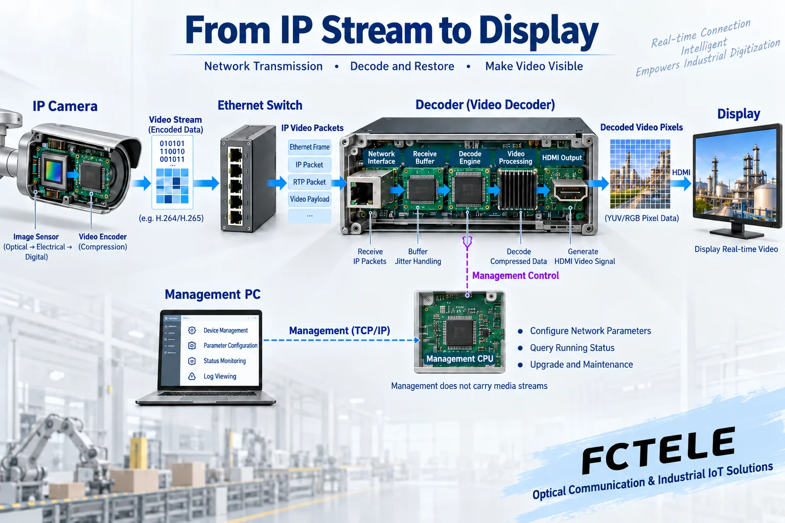
The camera first captures an image with a sensor, processes and encodes it into a stream, and then organizes it into network packets according to a transport protocol. Switches forward frames, and routing devices handle cross-subnet paths when needed. The receiving end retrieves the media data, and only after necessary buffering, de-encapsulation, and decoding does it obtain the pixels and timing used for display output.
De-encapsulation is extracting the media content from the transport structure, while decoding is interpreting the compressed content; they are not the same step. Taking RTP carrying H.264 as an example, the media data also needs to follow the corresponding packetization rules; supporting a certain encoding name does not prove that the device accepts all transport methods. A switch also does not directly turn the received compressed stream into an HDMI signal.
Confirm power, link, and management separately first
First check the power supply according to the actual device requirements, and observe whether it repeatedly restarts or reports an abnormality. Older drafts uniformly specify 12 volts, 6 watts, or startup within one minute, which cannot be taken as the standard for all decoders. The waiting process and indicator light meanings should be based on the manual; a lit light also does not prove that the power supply continuously meets requirements under load changes. Do not try to connect an unknown power interface.
After the network link is established, check the address, subnet, and required gateway, and confirm that the management computer can reach the device. However, a working management web page only indicates that the management path is available; the camera’s VLAN, media ports, or cross-network access may still be restricted. A failed ping does not necessarily prove that the video path is damaged; the device and network policy may prohibit such probing.
How to check the media source and authentication
The decoder needs to know from which source, using which protocol, to obtain which stream, and must have applicable permissions. The camera management account and media access permissions are not necessarily the same, and the main stream, sub-stream, and URL may also differ. Check the device’s official documentation, and do not treat another manufacturer’s address or anonymous access settings from an old article as a universal configuration.
The third-party Axis D1110 manual clearly lists the video source address, protocol, and camera account as access elements, and points out that some third-party sources require a URI provided by their manufacturer. This shows that obtaining media must have matching conditions, and does not prove that Feichang Technology equipment has all functions of that third party. Do not expose passwords or disable authentication for long periods for troubleshooting; first use an approved test account to confirm the connection.
Why can it still fail to decode after receiving data?
Even for the same H.264 or H.265, the encoding profile, level, resolution, frame rate, and stream organization may differ. Device support capabilities are limited, and multi-channel decoding usually also involves total resources. The actual output at the source should be checked item by item against the receiving end’s official support table, and you should not infer from the advertised maximum resolution that any number of channels or any frame rate can be displayed simultaneously.
Network loss, out-of-order packets, or waiting for a key frame may cause decoding to pause, produce blocky artifacts, or delay recovery. Buffering can absorb some arrival variations and also increases waiting; it cannot infinitely eliminate continuous packet loss or excess traffic. If you see picture stuttering, first compare the source bitrate, network counters, and decoding alarms, rather than unconditionally increasing the buffer or raising the bitrate.
Even if decoding is normal, check the display output
The decoded picture must be sent to the monitor through a display interface supported by the device, and the output resolution and refresh conditions must be accepted by the display. HDMI cables, input selection, and output format belong to this part of the path. If the monitor is switched to the wrong input or only supports certain timings, the network and decoding may be normal but there is still no picture.
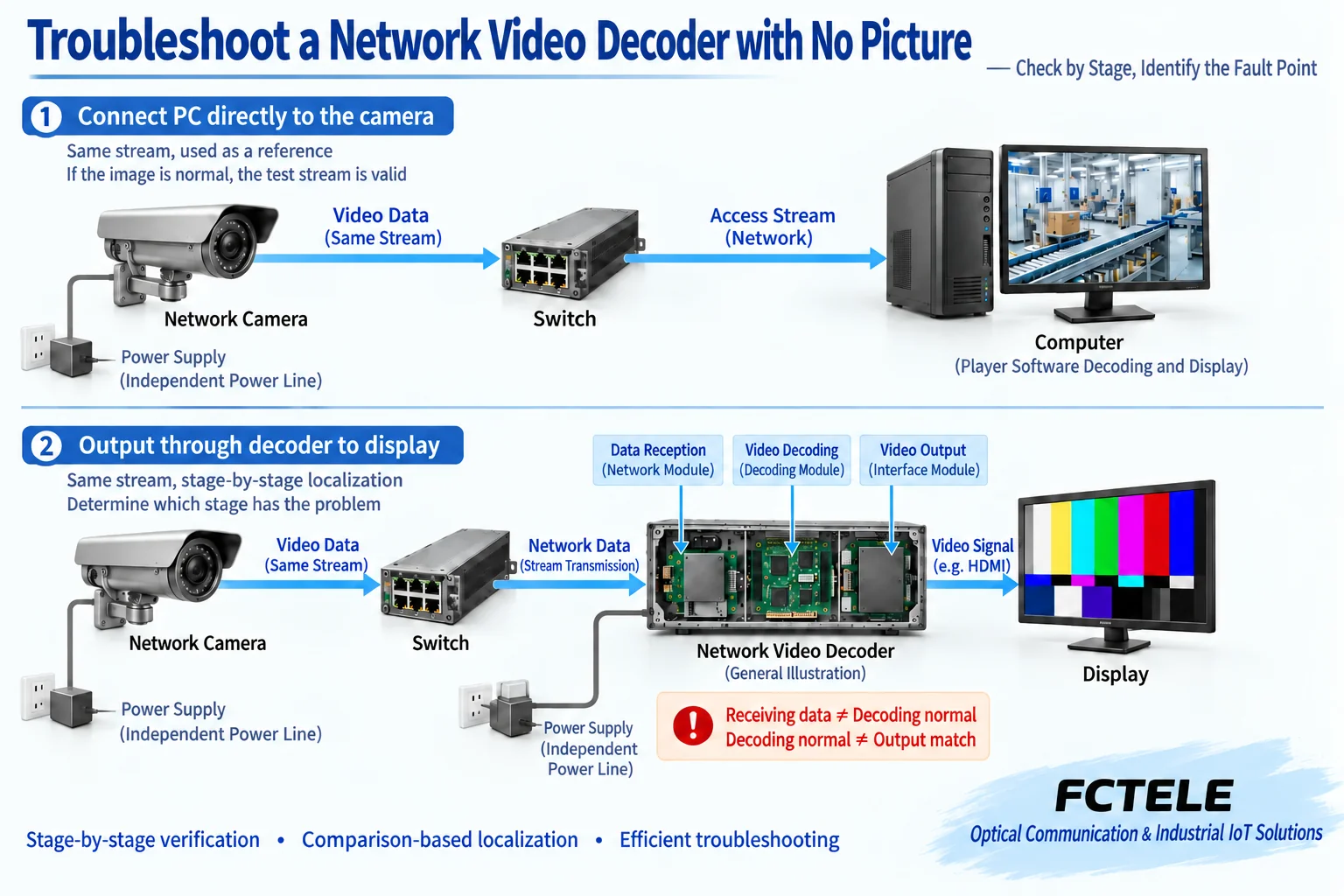
If the device provides a known test pattern, it can be used under the conditions specified in the manual to isolate the display stage; if this function is not available, compare with a known-good matching monitor and a short cable. You cannot attribute every system to an HDCP problem, nor judge the conversion direction or capability from the appearance of an adapter. First determine the identity of the output interface, then decide whether a matching converter is needed.
Use the same video for segmented comparison
Suppose the computer preview is normal but the decoder box has no picture. First confirm that the computer and the decoder box use the same source and the same stream, to avoid one taking the sub-stream and the other taking a more demanding main stream. Then check the receiving end’s session and supported parameters, and then test the display stage. The computer being able to decode shows that this test combination works, but does not prove that another device has the same decoding capability.
If all receiving ends are abnormal, go back to the source power, encoding settings, and common network path; if only the receiving end after a certain uplink is abnormal, check that path’s labels, policies, capacity, and error counters. Adjust only one factor at a time and record the result, save on-site logs, and do not immediately restore factory settings and lose the original address, permissions, and service configuration.
Boundaries of Feichang Technology dedicated video equipment
The Feichang Technology FCVV4 product details belong to a four-channel analog video optical transceiver; its video interfaces and optional auxiliary services can be used to check the corresponding analog surveillance link. It sends supported local services to a paired optical device, and you should not infer from having video and optical ports that it is a general IP video decoder. The company’s digital video optical transceiver category also requires confirming the input/output identity model by model.
If an existing project uses this kind of dedicated equipment, first check the actual video source such as BNC, the paired device, the optical path, and the opposite-end output, rather than setting a non-existent RTSP source. When IP decoding is needed, obtain specific model documentation that clearly marks media input, encoding capability, and display output; a public category name or picture cannot make up for missing capability evidence.
Acceptance to truly stable service
After restoring the picture, you should also verify audio, permitted control functions, continuous operation, and approved reconnection scenarios, and observe busy-hour bitrate and multi-channel load. Record the source configuration, receiving end version, network path, and display format for later fault comparison. One successful still picture cannot cover all dynamic pictures and simultaneous playback conditions.
Delivery documentation should be able to answer where the data comes from, how it is received and interpreted, and from which interface it is sent to the monitor, and retain fault-location evidence. Device firmware upgrades, resets, and restarts must be carried out according to maintenance arrangements and the manual, with backup first and a clear recovery method. The final judgment is based on actual video link acceptance, not fixed light colors, a uniform voltage, or guessed waiting times.
Documentation note: The schematic diagrams have been checked for technical content and are used to explain general mechanisms; they are not product photos or measured records. Specific interfaces, modes, and capabilities are subject to the selected model, version, and on-site verification.
Verification materials: Axis Network Video Decoder Configuration and Troubleshooting Manual
RFC 6184: RTP Payload for H.264
Feichang Technology FCVV4 Four-Channel Analog Video Optical Transceiver
Feichang Technology Digital Video Optical Transceiver Category
Related technical topics: How to configure switch command line: operation modes, running settings, and save verification How to choose an H3C switch series: boundaries for campus, data center, and industrial sites How E1 carries video and audio: encoding bitrate, framing, clock, and peer matching
Translated from the Chinese technical article. Source first published: 2020-01-19. Source last revised: 2026-10-13T03:22:35+08:00. Read the Chinese source
