


Choosing a fiber media converter manufacturer involves more than an enclosure and an industrial-grade label. Look for clear specifications, batch traceability and tests that cover the intended application. Good manufacturing and verification should support consistent operation of the same model under its specified power, temperature and link conditions. This article explains why optical conversion needs precise control and how to turn supplier introductions into verifiable evidence rather than performance guarantees inferred from promotional language.
1. Separate the complete unit, optical module and optical components
A typical Ethernet fiber media converter is a complete unit containing power circuitry, a copper interface, a physical-layer chip and optical transmission/reception components. A pluggable optical module is just one implementation of the optical interface; it contains emitting and receiving devices plus driver and receiver circuits. A complete-device manufacturer may purchase qualified modules or optical assemblies and perform circuit design, assembly and system verification without manufacturing every laser chip. When asking about in-house production, distinguish complete units, module packaging and semiconductor devices. A vague answer cannot replace a supply-chain explanation.
The physical layer directly processes line signals. In transmission, copper signals are received and processed, and the optical transmit circuit turns data changes into changes in emitted light. In reception, a photodiode turns incoming light into a small current, and amplification and decision circuits recover digital data. Switching chips, buffers and management depend on the architecture. The same optical-conversion label does not mean every product supports arbitrary protocols or speeds.
2. Optical assembly needs more than secure attachment
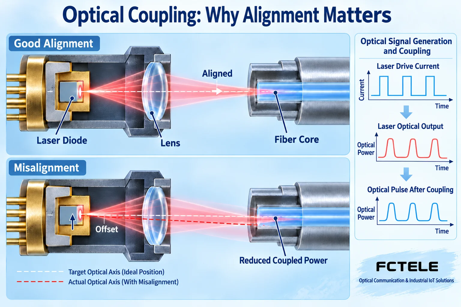
Light from the transmitter must enter the fiber core through optical structures inside its package. Coupling is the process of delivering light efficiently into the fiber. Misalignment of the emitter, lens or fiber can reduce coupled power, while dirty connector end faces add loss. Assembly must therefore ensure secure mounting and cleanliness and verify optical performance. This is a generic mechanism: whether a lens is used and how packaging and alignment work depend on the component design. It is not a view of a particular FCTEL production line.
Emitter output also depends on driving and temperature conditions. The driver supplies operating current and carries data modulation. Some designs use monitoring and compensation to stabilize output, but not every converter has the same feedback circuit. Reliability is not a matter of producing stronger light: receivers have permitted input windows and can malfunction above maximum input power. Manufacturers should provide verifiable transmit ranges, receive capabilities and operating conditions. Raising optical power in the field cannot fix every problem.
3. How soldering, power and cooling affect communication
PCB solder joints secure components and provide reliable electrical connections. Poor contact can cause intermittent faults during vibration or temperature changes. High-speed traces and connection structures also affect signal quality. Visual inspection finds only some defects and cannot prove every internal path meets design requirements. Ask how incoming inspection, assembly, powered tests and rework are recorded rather than merely whether inspection exists.
Power circuitry converts external input into chip supply voltages. Protection, regulation and cooling support stable communication, but one wide-temperature chip cannot prove the complete unit is wide-temperature rated. Power components, optics, connectors and enclosure cooling can each impose limits. Include actual cabinet temperature, supply fluctuations and mounting clearance in selection requirements. Surge, vibration and salt-mist claims need evidence for the model and test conditions; a metal enclosure does not prove them.
4. Why finished-product testing needs more than LEDs
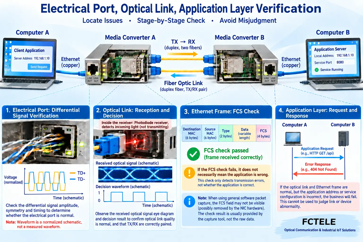
An illuminated LED normally indicates one condition, not correct frame transmission or application operation. Complete-unit verification should separately check stable power, copper and optical link establishment, errors under specified load and actual round-trip service. Test both directions: one transfer cannot prove the reverse receive path works. Reports should state port speed, optical pairing, fiber or attenuation conditions, frame lengths, load and duration so that results can be compared.
Ethernet frames carry data and checking information. The frame check sequence, or FCS, checks for transmission errors. Passing FCS does not verify application addressing, permissions or service, and ordinary software captures may omit it. Managed products can expose error counters and status; unmanaged equipment needs external test tools. Feasible tests depend on interfaces and tools. Sending a ping is not complete quality verification.
5. Use FCTEL product information as a verification starting point
The FCTEL B-series desktop Gigabit converter page lists Gigabit electrical/optical conversion and single-mode, multimode, single-fiber and duplex-fiber options. Use these interface conditions to build an inquiry checklist. Single- and dual-fiber versions have different pairing requirements; a distance alone cannot replace wavelengths and directions. For remote monitoring, check the managed single-optical/single-copper Gigabit product, whose page lists OAM, SNMP and link-status management. Management helps expose status but cannot replace power budgeting, power-supply checks and traffic tests. Other FCTEL series do not automatically have the same functions.
Require quotations to identify exact models, optical configurations, power accessories, management method and firmware version. A sample result cannot automatically cover similar-looking units with different components or configurations. Ask how production changes, substitute parts and firmware upgrades are identified and communicated. If detailed process information is unavailable, reduce uncertainty through specifications, sample retesting and delivery-consistency checks rather than inventing manufacturing capabilities.
6. Meaningful incoming acceptance tests
Check model labels, serial numbers, accessories and specification versions, linking approved samples to delivered batches. Before power-up, confirm voltage, polarity and installation conditions; never look into an optical port. Establish a known-compatible short-link baseline, then introduce the field link and save endpoint status, error counts and actual service results. Qualified personnel should conduct thermal, electrical and loaded tests under agreed conditions. Do not dismantle devices, bypass protection or apply voltage beyond specifications.
Distinguish inspected, tested-and-passed and unverified items in acceptance records. An intact enclosure, a lit link LED and continuous video are different evidence, not an unlimited reliability conclusion. Record conditions, batch and reproduction steps for faults before discussing them with the supplier. Clear evidence helps resolve problems more effectively than brand slogans.
Reference note: generic mechanisms refer to Analog Devices optical-transceiver explanations. Model selection refers to FCTEL B-series desktop Gigabit and managed single-optical/single-copper product pages. Illustrations show generic mechanisms. Figure 2 reuses a checked layered-verification diagram and does not represent model measurements or a production line.
Optical transceiver driving and control mechanisms·FCTEL B-series·FCTEL managed products
Translated from the Chinese technical article. Source first published: 2024-08-06. Source last revised: 2026-10-13T16:50:29+08:00. Read the Chinese source
