


Fiber optics transmit changes in light, not an extended electrical wire
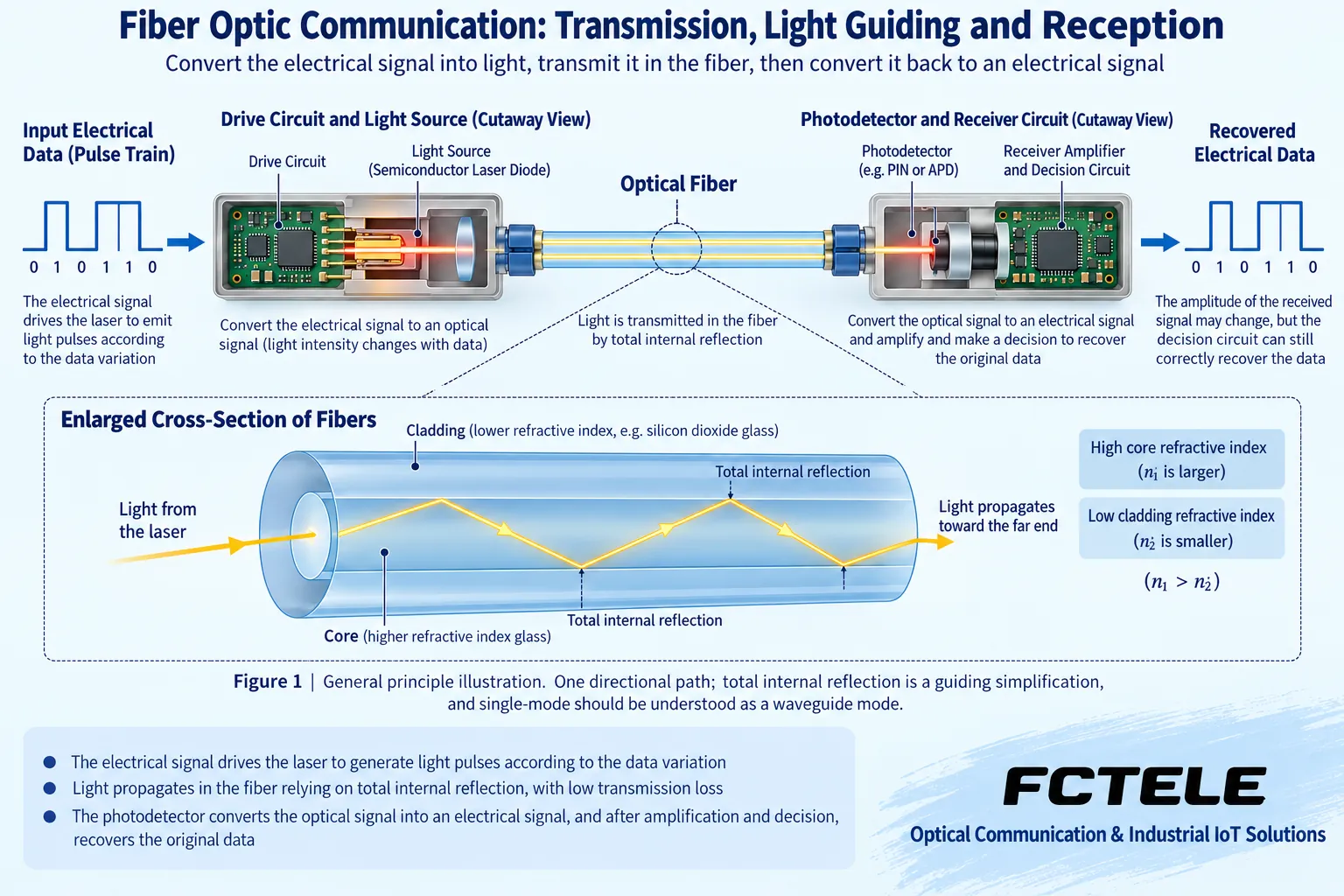
Fiber optic communication uses optical signals propagating in fiber to send information to a remote end. Understanding it as one common path in digital communication, the transmit circuit maps data to changes in light, and the receive circuit detects these changes and recovers the data. It is not letting the original current flow directly through glass, nor is it stuffing a whole picture as a complete object into the fiber.
Different services first go through their respective interface processing, which may be Ethernet frames, serial port data, or video sampling sequences. Using the same type of fiber does not mean the external interfaces and protocols are the same; a serial port optical modem will not thereby become a general-purpose network switch. Both ends must support the corresponding service and a compatible transmission method.
The transmitter first adapts the information to the light source
In common implementations such as direct modulation, the driver circuit controls the light source so that the output light changes with the electrical signal. The system may also use other modulation structures, so not all optical links can be summarized as a laser simply switching on and off. The light source type, wavelength, and output conditions should be confirmed by the selected equipment.
The optical port couples light into the fiber. Dirty end faces, mismatched connectors, or incorrectly installed modules can affect the link right at the starting point. The negotiated speed of the electrical interface and the line conditions of the optical interface are not necessarily the same and need to be checked separately. Changing to fiber can change the medium and distance conditions, but it will not automatically turn the original 100 Mbps service into 10 Gbps.
Why the core and cladding can guide light
In common glass fiber, the core has a higher refractive index than the cladding. Refractive index describes how light propagates in a material, and a suitable structure causes light to form a confined propagation along the fiber. A diagram of total internal reflection at the interface can help understand light guiding, but the cladding is not an inner wall coated with a metal mirror, and the fiber is not a hollow tube.
Single-mode fiber is better explained using waveguide modes; one geometric ray repeatedly reflecting back and forth cannot be taken as all the internal details. Multimode and single-mode differ in propagation and connection conditions, and the core size, module, and operating wavelength need to match. After choosing the fiber type, the entire line and the opposite end should also be checked, not just the patch cord color.
Guiding light does not mean optical power is completely preserved
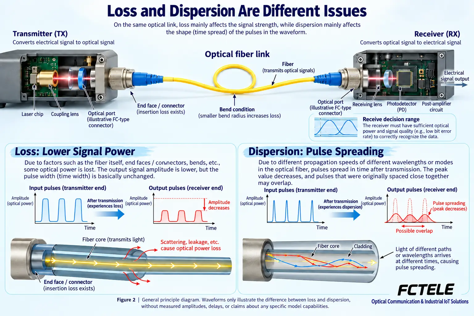
Material absorption and scattering reduce optical power along the line, and connectors, fusion splices, and bends that do not meet requirements also add loss. The fact that light can be guided does not mean it will not weaken. The longer the line and the more events, the more calculation and measurement are needed based on actual conditions; the effect of cable quality on transmission cannot be ignored.
The loss budget compares the available conditions at the transmitter and receiver with the fiber and connection events, and an appropriate engineering margin must also be reserved. The received power must not only not be too low, but also must not exceed the allowed range of the receiver. Connector cleaning and testing are part of optical path work and cannot be replaced by equipment price or advertised distance.
Dispersion discusses how pulses spread
Loss mainly discusses power reduction, while dispersion mainly discusses signal spreading in time. For example, different propagation conditions cause some components of an optical pulse to arrive earlier or later, so an originally narrow pulse may become wider; when adjacent data intervals are very short, the receive decision may be affected. Sufficient power does not automatically prove that the time waveform is also acceptable.
A waveform illustration can only show this kind of change and does not represent measured results from a particular on-site cable. Dispersion, bandwidth, and the signal processing conditions of the module affect the usable rate and distance. You cannot infer that any device has unlimited bandwidth just because the optical frequency is very high; actual systems also have limits from electronic circuits, coding, reception, and service resources.
How the receiver hands the light back to the equipment
A photodetector converts the received changes in light into an electrical signal, and subsequent circuits perform suitable amplification and processing. A digital link may also need decision and timing recovery so that the output meets the corresponding interface requirements. The receive circuit cannot understand data just by seeing a little light; it must be within the supported signal and operating range.
Optical amplification and electrical amplification after reception are also not the same task. Even if the circuit can increase amplitude, information lost at the source, format mismatch, or severe distortion is not guaranteed to be recovered. Troubleshooting should look separately at optical power, error records, line and interface configuration, and accept physical connection success and application communication success separately.
What conditions must be checked simultaneously for a complete path
Taking an Ethernet extension link as an example, first confirm that the copper port service enters compatible equipment, then confirm the optical path from the transmitter to the receiver at the opposite end. Dual fiber usually carries directions separately, and single-fiber bidirectional needs paired transmit and receive conditions. Do not mistake two fiber cores for two backup links, and do not assume they can be paired just because the product names align.
The Feichang B series classification and one fiber port and four copper Ethernet ports details provide an entry point for selecting optical-electrical access. When multiple electrical ports share an uplink, capacity needs to be evaluated according to the actual service load; a good fiber line cannot eliminate uplink congestion. The text for some electrical port speeds in the details differs, and should be confirmed according to the clear specifications and delivered version; this article only describes media conversion and multi-port forwarding based on their interface tasks.
Acceptance at both the optical path and service levels
First establish a baseline with a known compatible short link, then add the formal line, recording the module, fiber core, wavelength, end face, power supply, and receive conditions. Use suitable instruments and methods when measuring insertion loss or locating events; a single port light being on cannot be taken as a complete record. Fiber does not carry copper-port PoE power, and remote devices still need independent confirmation of power supply.
Then verify real communication and representative load, observing errors, packet loss, and link recovery after disconnection. Fiber reduces electromagnetic coupling in the transmission medium, but it does not automatically protect equipment power supplies, copper cables, and cabinets from interference; an optical link also does not automatically encrypt services. Save topology, port, and test records so that when a fault occurs, you can determine segment by segment where the problem is.
Reference note: The principle diagrams have been checked against technical content and are used to explain general mechanisms; they are not product photos or measured records. Specific interfaces, modes, and capabilities are subject to the selected model, version, and on-site verification.
Verification references: FOA: Total internal reflection and light guiding
FOA: Fiber structure, loss, and dispersion
FOA: Optical data links and budgets
Feichang B series fiber optic transceivers
Feichang one fiber port and four copper Ethernet ports transceiver details
Common on-site questions
Does fiber guide light because there is a metal mirror surface or hollow pipe inside?
No. Common glass fiber uses the refractive index structure of the core and cladding to form confined propagation. A total internal reflection ray diagram helps for beginners, but single-mode also needs to be understood with waveguide modes; the simplified reflecting ray cannot be taken as all internal details. Fiber type, module, and wavelength must match, and patch cord color alone cannot prove compatibility.
Loss and dispersion both make the signal worse; can increasing optical power solve both at the same time?
They cannot be treated as equivalent. Loss mainly appears as power reduction, while dispersion spreads the pulse in time; sufficient power may still make decision difficult. Increasing transmit power may also exceed the allowed receive range. Loss, rate, and transmission conditions should be checked separately, and you should not assume a device has unlimited bandwidth or arbitrary distance capability just because the optical frequency is high.
If a 100 Mbps device is connected to fiber, can it simultaneously upgrade speed and obtain remote PoE?
These capabilities are not obtained automatically. Service rate is limited by the interface and device processing, and glass fiber does not carry copper-cable PoE power. Remote power supply and multiple electrical ports sharing an uplink should be planned separately. Acceptance should look at optical path pairing and loss, and also run real services and peak loads; do not treat media conversion as a comprehensive upgrade.
Continue reading: How does an optical modem transmit signals? Principles of electrical-to-optical conversion and receive recovery ; How far can an optical modem transmit: Optical power budget, receive overload, and on-site acceptance ;
Translated from the Chinese technical article. Source first published: 2024-10-31. Source last revised: 2026-10-15T22:31:43.863560+08:00. Read the Chinese source
