


The sockets on an industrial switch cannot be identified by shape alone. Network ports and optical ports carry service data, Console lets maintenance personnel enter the device, power terminals supply the whole unit, and alarm contacts report status to external systems. Understanding these four paths explains why “it fits” does not equal “it is connected correctly.” This article first explains how interfaces work internally, then provides a method from panel identification to service acceptance.
1. First look at purpose, then look at the plug
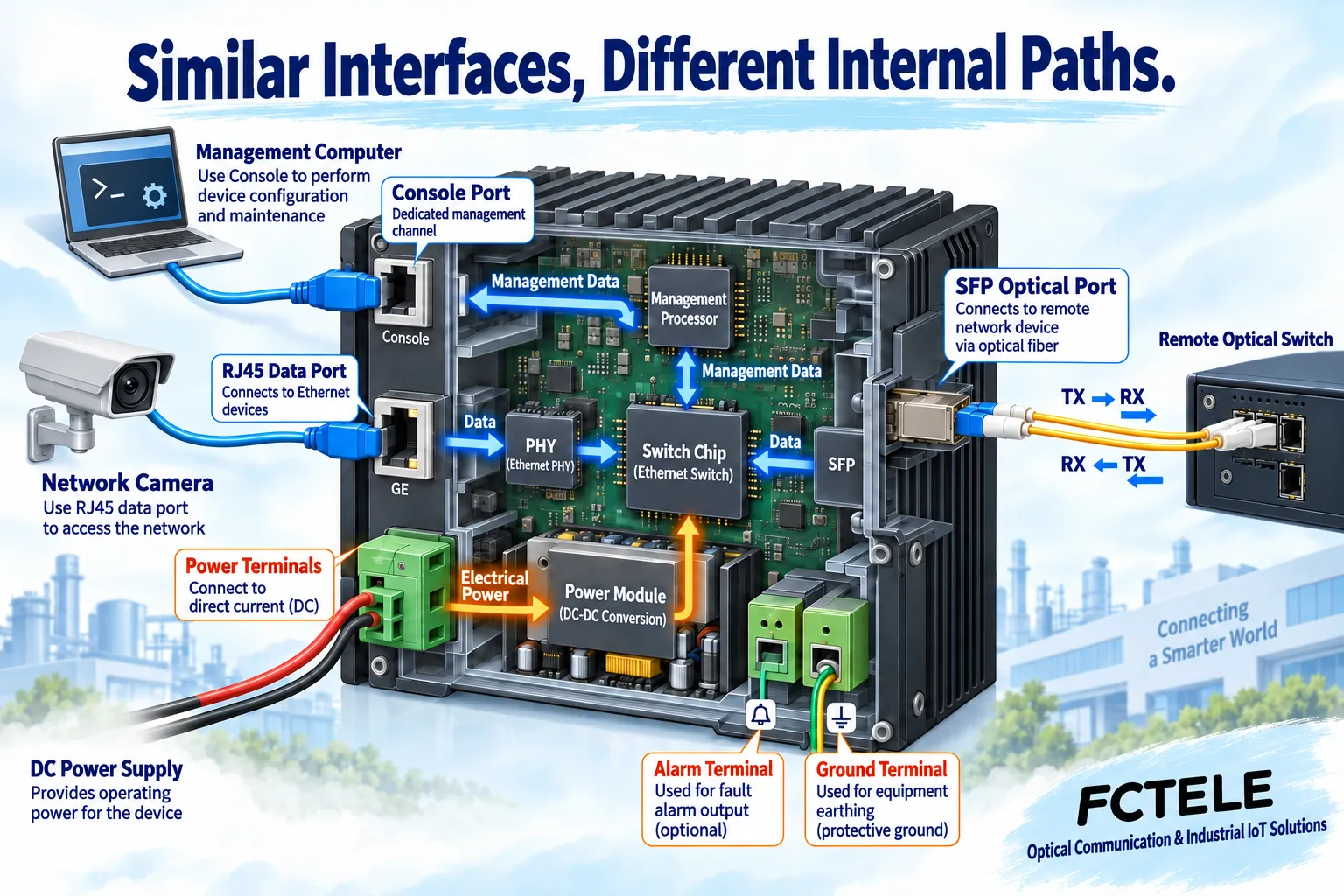
Suppose a workshop needs to connect cameras, controllers, and a remote equipment room. The camera’s network data enters the switch through a data port; a maintenance computer may modify configuration through another interface; an external power supply continuously provides energy. Three things happen on the same device, but the internal circuits are not the same. Therefore, the first step in interface planning is not to prepare several network cables, but to clearly write down what each port connects to, what it transmits, and what it is used for.
Taking the common RJ45 shape as an example, sockets marked LAN or with port numbers usually carry Ethernet traffic; sockets marked Console may be serial management entrances. Both can accept plugs of similar shape, but may have different electrical definitions and protocols. Serial management is like a service channel used by maintenance personnel, not another high-speed data path; this analogy only explains the purpose, not pins, voltage, or wire order.
2. RJ45 electrical ports restore electrical signals into data
Ordinary Ethernet electrical ports transmit signals through twisted pair. Two wires are twisted together, and the receiving circuit identifies signals based on the voltage difference between the wire pairs, which helps resist some common-mode interference. The physical layer transceiver in the port, that is, the PHY, is responsible for converting the signals on the wire into data that the chip can process; the switch chip then decides which data port to send from based on the forwarding table.
Common 1000BASE-T gigabit copper Ethernet uses four pairs, and it cannot be assumed that “as long as two wires are connected” it will run gigabit stably. Copper channel length, cable category, termination, and interference environment all affect the result, and an industrial switch will not automatically cancel cabling boundaries. Older materials broadly wrote common gigabit copper as 1000BASE-TX, which is easily confused with 1000BASE-T; when selecting, directly check the standards and cable conditions supported by the model manual.
When both ends support auto-negotiation, they negotiate the speed and duplex mode that both can use. A link light being on only indicates that a certain degree of physical connection has been established, and does not prove that VLANs, addresses, and applications are all correct. When speed drop is found, record the actual negotiated speed and error counts, then check cables and port configuration; do not judge only by indicator light color, because the meaning of light colors may differ between devices.
3. SFP, fiber connectors, and speed are not the same concept
SFP is a form of pluggable transceiver module, and the slot is the position where the device connects to the module; LC, SC, etc. are names of fiber connectors. You can understand the slot as a seat that adapts modules, and the connector as the position where the module is wired, but similar seat shapes do not mean all modules are compatible. Some modules are optical modules, and copper cable modules also exist; seeing SFP does not mean it is uniformly a certain fiber specification.
An optical module converts electrical signals into optical signals, and the remote module restores them to electrical signals. When matching, simultaneously check the modules supported by the device, speed, single-mode or multimode fiber, transmit and receive wavelengths, allowed distance, and optical power conditions. Merely changing to a longer-distance module does not guarantee that the original fiber and connectors can meet the requirements; received power that is too low or too high can both cause problems, and thresholds are based on specific module data.
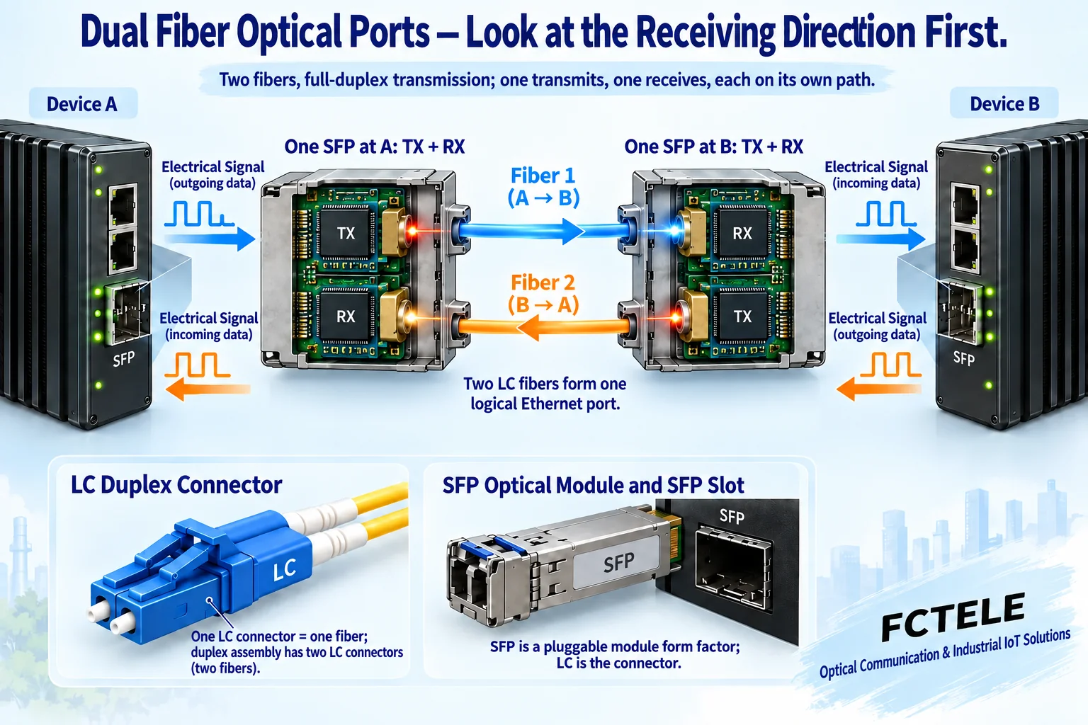
Dual-fiber wiring requires the local TX, that is, the transmit end, to connect to the opposite RX receive end; the other fiber carries reverse transmission. Single-fiber BiDi uses one fiber core to carry both directions simultaneously, distinguished by different wavelengths, and a matching pair of modules must be purchased. After connectors are clean and transmit/receive directions are correct, actual services still need to be verified. Do not look directly at an operating optical port or observe fiber ends with an ordinary magnifying glass; end-face inspection should use suitable tools and safe methods.
Port count, Combo, and module delivery must be confirmed separately
The TX and RX of a dual-fiber module are the two directions of the same full-duplex link: at the local end it is usually counted as one logical Ethernet port, not two data ports because two fibers are used. Single-fiber BiDi also usually corresponds to one local logical port, only sharing one fiber by means of complementary wavelengths. Port count, fiber core count, and module count at both ends must be listed separately: connecting two devices still requires a matching transceiver at each end.
Combo is a common name for a shared copper/fiber port. One set of RJ45 connection positions and an SFP slot share one logical port, and cannot be treated as two independent data ports that can work simultaneously. Media priority, automatic selection, and manual switching methods should be checked according to the specific manual; a device with two independent ports is not this relationship. First check the panel numbering and port configuration page, then choose to connect copper or fiber, and do not copy commands from other manufacturers. You may refer to Cisco’s explanation of Combo interfaces to understand the general mechanism, but do not conclude from this that any Feichang Technology model has Combo functionality.
A pluggable SFP slot itself does not mean an optical module is included in the shipment. Fixed optical ports and pluggable solutions cannot be confused either. When ordering, write the complete switch model, module model and quantity, wavelengths at both ends and fiber type, patch cords, and connectors separately into the configuration list; whether modules are included in the quotation and packaging is subject to order confirmation and accompanying materials. Do not carry over the old article’s blanket guarantee that “buying a photoelectric switch means the manufacturer must have configured it.”
Circular interfaces and legacy interfaces do not have capabilities presumed from appearance
M12 describes a connector series, not a unified guarantee of speed or protection rating. Coding, pin count, wire order, and the Ethernet standard supported by the device must match; protection performance also depends on plug matching, tightening status, and installation conditions. The Feichang Technology official website hasM12 interface industrial switch category, and selection still requires checking specific model data; do not treat a circular appearance as a gigabit or waterproof certificate.
AUI, coaxial BNC, and FDDI in older materials belong to historical network background, and similar plugs cannot be connected to current switches just because they look alike. BNC on other devices may also carry video or other signals, and FDDI is not equal to ordinary Ethernet; connecting legacy devices requires first confirming their network technology and required converters. SC and LC connectors contact the fiber end face, not a copper post used to identify optical ports. Read interface labels and manuals first, and do not try unknown terminals by trial and error.
4. PoE adds controlled power on network cables
PoE refers to supplying power to terminals through Ethernet cables. A power sourcing end supporting standard PoE identifies the powered device according to the corresponding process, then supplies power according to the supported class and capability; it is not directly applying voltage on any network port. Data and power use the cable simultaneously, but single-port power, overall power budget, upstream power supply, and cable loss all have limits.
For example, several cameras can work during the day, but at night when fill light turns on, power demand may increase. If total demand exceeds the budget, the problem may be in power supply and power allocation, not the fiber link. When planning, check the terminal’s maximum demand, power supply standard, and the actual selected version of the device. Non-standard passive power supply devices cannot be judged by the detection and protection conclusions of standard PoE, and do not mistakenly connect ordinary Ethernet ports to unknown power supplies.
5. Management, power, and alarms are each checked separately
Console is often used for local diagnosis and requires cables, electrical definitions, and serial parameters specified by the manufacturer. Network management is entered through the device management address and supported services, such as Web or SSH. The two entrances cannot replace each other in judgment: if the management page cannot open, it may be an address, routing, access restriction, or service configuration problem, not necessarily a damaged data port. For first maintenance, change default credentials, save configuration, and keep a backup.
Power input must be checked against the complete model and nameplate; do not apply the terminal definitions of a certain dual-DC power device to an AC version. Protective grounding also cannot be casually used as a signal return wire. Power installation should be performed by qualified personnel according to the manual, and do not try by trial and error, disassemble, or short unknown terminals while energized. Whether dual inputs form effective redundancy also depends on whether there is a common failure point in the upstream power supply.
Alarm terminals may be relay dry contacts, whose function is to report status through contact opening and closing, not to directly provide load power. Check the common terminal, normally open or normally closed, rated load, and trigger conditions, then let a compliant external circuit collect them. Some special switches have an additional service serial port, which is not the same function as the Console management port; whether serial data to network is supported must be checked in that model’s service description.
6. Use a small link to establish an acceptance baseline
First let one terminal connect to a test computer through one electrical port, confirming physical link, address, and real request response; then add a fiber uplink and verify bidirectional services separately. Change only one condition at a time, and record port number, negotiated speed, module information, error counts, and test results. When a ring network is needed, configure it according to the supported protocol; do not directly connect several ordinary data ports into a circle.
The Feichang Technology official website’s “mini industrial rail-mounted managed with RSTP ring network 4 gigabit electrical + 2 gigabit optical” product data lists four gigabit electrical ports, two gigabit optical ports, and power and PoE options. This combination can let near-end terminals use copper cables and remote uplinks use fiber, but when ordering it is still necessary to check the specific optical port implementation, module matching, and power version. Interface count solves access location, protocols and configuration determine how to forward, and only when both are correct is it a complete solution.
References:Feichang Technology industrial switch product categories, 4 electrical 2 optical product details, Cisco industrial switch interface and cable manual. Third-party manuals are only used to explain interface classification, not as Feichang Technology pin definitions. The illustrations are general principle diagrams, not physical photos or measured data.
Translated from the Chinese technical article. Source first published: 2019-07-18. Source last revised: 2026-10-13T11:37:04+08:00. Read the Chinese source
