

Onboard industrial Ethernet switches can carry Ethernet services such as passenger information displays, video surveillance and maintenance communications. Compared with office networks, onboard installation pays more attention to vibration, power supply changes, temperature, electromagnetic compatibility and connection reliability. This article discusses general information services and does not treat ordinary industrial switches as train safety control equipment.
How the picture passengers see is sent to the screen
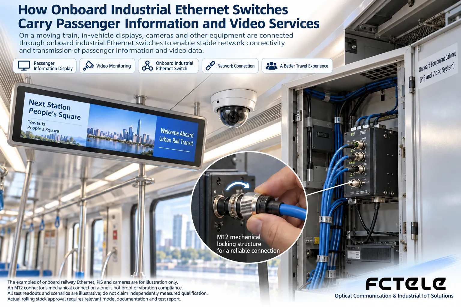
A passenger information system usually consists of content sources, management equipment, a network and display terminals. Switches send data from servers or control terminals to the corresponding screens, and camera images can also be aggregated through the network to recording or monitoring equipment. The picture content is provided by the service system; the switch itself does not generate station information or identify passenger events.
When each carriage has multiple terminals, you should distinguish access links from cross-carriage uplinks. Video and display content may occupy bandwidth at the same time, and uplink capacity needs to be measured according to real bitstreams, update methods and peak demand. Counting only the number of terminals cannot determine how much bandwidth is needed.
Why mechanical connections also affect the network
Vibration may loosen connectors, wear wiring harnesses or cause equipment fixing to fail. Onboard scenarios use suitable fixing methods and locking connectors; M12 is one possible interface form, but the interface name cannot prove that the whole device already meets a certain onboard requirement.
You need to check connector coding, pins, rate, cable, locking method and installation process. Different M12 interfaces are not freely interchangeable, and not all industrial switches use M12. Wiring harnesses should be fixed according to project requirements, and maintenance space and connector stress also need to be considered.
Power supply and temperature are not accessory issues
Equipment must adapt to the actual onboard power supply and its changing conditions; a certain DC rated voltage cannot be treated as the entire supply range. Protection, grounding and isolation requirements should be confirmed by the vehicle and equipment documentation. An unverified conversion power supply may become the cause of intermittent link failure.
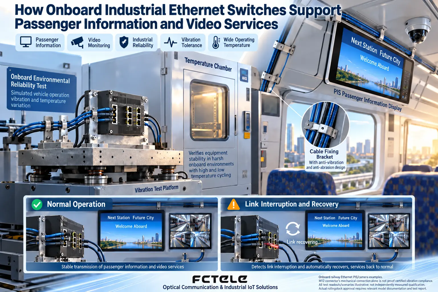
Ambient temperature and the device’s own heat generation together determine the internal state. When installed in a closed cabinet, the cabinet temperature rise and adjacent heat sources may make the temperature around the device higher than the carriage temperature. A wide-temperature label should be understood together with test conditions, load and installation method, not just by looking at the enclosure material.
Network functions should be selected according to services
VLAN can divide broadcast domains, multicast management may reduce unnecessary video traffic, and QoS can control service priority according to the actual implementation. However, these functions require joint configuration of terminals and the system. After placing multiple ports into different VLANs, cross-subnet communication usually also requires corresponding routing and access policies.
If redundant connections are used, the protocol, device compatibility and fault recovery requirements must be clarified. Directly connecting network cables into a ring may create a broadcast loop; you cannot assume that a device automatically handles any loop just because it is called an “industrial switch.” Recovery time should be measured in the actual system, not replaced by a protocol name.
Acceptance should be carried out separately from screens, video and logs
First check whether normal services are complete, then check error counters, packet loss and terminal displays. Video being playable does not mean information display updates normally, and network link recovery does not mean the application automatically reconnects. The recovery process and abnormal prompts should be recorded according to each service requirement.
Tests involving onboard systems should be carried out in an authorized environment and within specified windows. Device or link interruption tests must not be carried out arbitrarily on operating vehicles. Delivery documentation should leave version, port, wiring harness, configuration and maintenance methods to facilitate subsequent equipment replacement.
When selection is needed, you can use Feichang Technology Product Center to check specific models, and then request applicable standards and test evidence. A certain model’s certification from other manufacturers can only serve as a reference for understanding requirements and cannot be transferred to unverified products.
The illustration is only a general PIS and video communication scenario and does not represent actual train system configuration, certification or guaranteed performance.
Translated from the Chinese technical article. Source first published: 2019-06-08. Source last revised: 2026-10-13T23:07:12+08:00. Read the Chinese source
