


The progress of optical communication is not just about making a single fiber run faster; it also solves capacity, distance, energy consumption, and management problems at the same time. The old article used “the next five years” to predict commercial timelines, which is no longer suitable as a basis for today’s procurement. This article instead explains the working mechanisms behind ten technology directions: which ones change the signal, which ones change the components, and which ones change how the network is organized. Understanding these differences is more useful than memorizing a string of popular abbreviations.
First, understand the most basic optical link
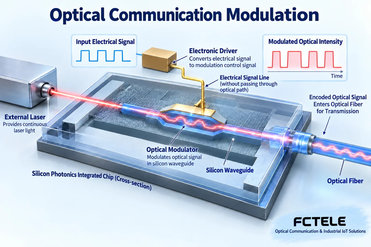
A computer generates electrical signals, while an optical fiber carries light. The transmitting device first uses a driver circuit to control a light source or modulator, making some characteristic of the light change with the data; the receiving device uses a photodetector to convert the arriving light into current, then amplifies, decides, and recovers the data. Light does not directly move the entire photo on the screen to a distant place; it carries encoded information. You can understand the link as switching to a different transport vehicle, but this analogy cannot explain exact rates and bit errors. Device interfaces, encoding, fiber, and receiving capability must match; otherwise, even if there is light, there may not be usable data.
Directions one and two: silicon photonics integration and closer optical interconnection
Silicon photonics uses semiconductor manufacturing processes to make optical functions such as waveguides, modulators, and detectors into compact devices. A waveguide can be understood as a light channel on a chip, a modulator is responsible for writing electrical data onto light, and a detector completes the opposite process. It does not make ordinary silicon wafers emit light out of thin air; the laser source still involves materials and integration approaches. Reducing discrete components and long electrical connections may improve density and energy consumption, but packaging, heat dissipation, coupling, and yield are still important. Optical interconnection gradually moving closer to computing chips is to shorten the path that high-speed electrical signals must travel; it does not mean that all computing logic switches to light, nor does it mean that existing equipment can be upgraded by just changing one cable.
Directions three and four: increasing single-channel capability and wavelength division multiplexing
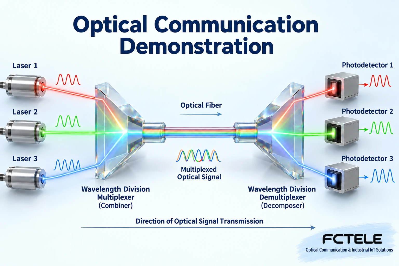
To increase single-channel capability, you can use a higher symbol rate or make one symbol express more information. A symbol is a signal state that the receiver distinguishes once; when there are more states, adjacent states are harder to distinguish, and the requirements for noise, distortion, and receiving processing also increase. Wavelength division multiplexing, on the other hand, lets carriers of different wavelengths share a fiber and then separates them at the receiving end. It is like different lanes running in parallel, but actual optical channels still require filtering and wavelength stability. Making a single channel faster and increasing the number of channels are different methods and are often used together. You cannot simply multiply the number of channels by the nominal rate and treat that as application throughput; encoding, error correction, and protocol overhead also consume resources.
Directions five and six: coherent reception and advanced digital processing
Direct detection mainly observes changes in light intensity, while coherent reception mixes the received light with a local reference light, enabling the receiver to obtain more signal characteristics. The reference light is like a ruler for measurement, not a replacement for the remote transmitted data. Digital signal processing then compensates for transmission impairments within a certain range, and forward error correction uses added redundancy to help recover errors. They expand the space of available options, but they cannot infinitely rescue an arbitrarily damaged link. Different distance, capacity, and power consumption goals require trade-offs, and one cannot simply conclude that one reception method is better everywhere. Readers should also distinguish between “improving reception tolerance” and “the line has no attenuation at all”; the latter does not hold.
Directions seven and eight: flexible optical switching and IP-optical coordination
An optical network not only has straight-line transmission; it also needs to send services to different nodes. Reconfigurable optical add/drop multiplexing equipment can select, add, or remove wavelength channels according to its designed capability, reducing the need to rewire every time an adjustment is made. Flexible spectrum further changes the spectrum arrangement occupied by channels, but it must be supported jointly by equipment along the entire path. The IP layer handles packet routing, and the optical layer handles bearer and optical channels; coordination between the two can reduce waste caused by isolated planning. Optical-layer reachability does not mean IP routing is correct, nor does it mean a certain service has already obtained a bandwidth guarantee. Actual construction still requires checking the optical budget, routing policies, protection methods, and operations boundaries.
Directions nine and ten: software control and green operations
Software-defined networking moves some control decisions away from individual devices, with a control platform organizing configuration and resources. The platform can reduce repetitive operations, but controllers, device interfaces, permissions, and fault handling all need to be designed; software does not eliminate fiber bends or connector contamination. Green communication focuses on how much energy is consumed per unit of effective service, including chips, lasers, power supply, and cooling. If low-power devices require more equipment to make up for capacity, the total system may not necessarily save power. When comparing, load, port utilization, and cooling conditions should be placed within the same boundary; you cannot use an idle power number to replace operating cost.
A selection example a beginner can use
Suppose two equipment rooms need to be interconnected. First record the service peak, actual distance, existing optical cable, and future expansion method. If only a small number of links are needed, suitable pluggable modules may already be enough, and there is no need to rebuild the entire network just to chase the terms silicon photonics or coherent. If fiber cores are tight and multiple services must run in parallel, then evaluate a wavelength division solution; if there are many management nodes, then consider centralized scheduling. At each step, ask “which bottleneck of mine does this mechanism solve?” Asking the solution provider for a compatibility table for both ends, power budget, service testing, and recovery process is more likely to reveal problems than only asking about the highest rate. This example is an explanation of thinking and does not correspond to any actual customer or model promise.
How to read technology trends without being misled by predictions
Divide the content in the material into four categories: defined mechanisms, released products, experimental demonstrations, and time predictions. Success in a laboratory under certain conditions does not mean all equipment rooms can directly reuse it; one vendor supporting a feature also does not prove that other brands have the same implementation. The general directions mentioned in the article do not constitute specific model specifications for Feichang Technology. Check the material date, test conditions, interface specifications, and purchasable status, and keep verification records before upgrades. Final acceptance should cover capacity, bit errors, optical power, alarms, and maintenance processes at the same time. The core of understanding evolution is knowing where performance improvements come from and what conditions they cost, rather than believing that all new technologies will immediately replace old ones.
Industrial and transportation applications: optical links carry services, they do not make decisions for terminals
Factories sending remote instrument data to a control room, and transportation sites connecting cameras or roadside terminals to a center, may both use optical fiber. But the services must first be clearly distinguished: serial ports, analog quantities, E1 leased lines, dedicated video, and Ethernet have different interfaces and processing methods. The same optical fiber can be used by different systems, but it cannot make any two optical devices interoperate. Optical transmission handles the handover of information, while control algorithms, video analysis, and scheduling decisions are still completed by the corresponding terminals and software.
For example, an IP camera first outputs Ethernet frames, which are then sent to the center through matching switching and optical ports; if an analog camera is to enter an IP system, corresponding encoding equipment is also needed. If an instrument outputs RS485, an interface or gateway solution that supports it should be used, and it cannot be directly plugged into an ordinary network optical port. This example is only a division of tasks, not an actual customer case, and it certainly does not mean that switching to optical fiber will automatically recognize the instrument protocol or guarantee control real-time performance.
The Feichang Technology product center’s managed industrial rail-type 10-gigabit 4-optical 8-electrical layer 3 switch provides a candidate for optical-electrical Ethernet access and aggregation, and the material lists optical ports, electrical ports, and network management functions. It can be used to check network service requirements item by item, but this article’s silicon photonics, coherent, or wavelength division trends do not imply that this model has these technologies; nor should a network product be understood as a general-purpose telephone, serial port, or analog quantity conversion device. Selection still requires checking the ordered version, matching modules, optical budget, and actual service load.
Optical fiber can reduce the corresponding electromagnetic coupling in the transmission medium, but on-site power, short copper cables, grounding, temperature and humidity, and maintenance still need to be handled separately. Increased capacity, reduced latency, or improved reliability must specify which path segment, what load, and under what conditions the result applies. An increase in wireless access services may bring bearer demand, but it cannot be claimed on that basis that all optical transmission equipment supports any mobile communication interface.
Here we discuss optical communication equipment used to transmit information. Laser surgery uses the interaction between light and tissue, and photoacoustic imaging involves another detection mechanism; they cannot be classified as the same communication application just because they both use light. The mixed discussion of these concepts in the old article is not a basis for merging them. The practical value of technological evolution is to make specific services more suitable under verifiable interface, capacity, power, and maintenance conditions, rather than having a “future technology” name cover all scenarios.
Material note: The two figures are general principle illustrations made with AI assistance and checked for content; they are not actual products or measured results. The beam colors and waveforms are mechanism symbols and do not indicate communication light visible to the naked eye or real dimensions.
Principle verification materials: Official material 1 ; Official material 2 . The general mechanisms and examples in the text do not replace the corresponding model manuals. Feichang Technology managed industrial rail-type switch interface material
Translated from the Chinese technical article. Source first published: 2019-06-28. Source last revised: 2026-10-13T09:28:05+08:00. Read the Chinese source
