


Serial server network settings need to solve three things: what address the device uses, how data reaches the other end, and which service the application connects to. IP, mask, gateway and DNS each have their own responsibilities; communication does not happen just by filling in a few default values. First confirm management access on an isolated test network, then establish the application connection, and finally verify the real response of the serial device. Only then can you distinguish between “the web page opens” and “the system is usable.”
1. The address finds the device, the port finds the service
The serial circuit of the serial server receives bytes from the instrument, buffers them, and hands them to the network protocol stack; the Ethernet interface sends network frames onto the cable. In the reverse direction, it receives network data and sends it to the terminal according to the serial parameters. Network settings determine how data reaches the device, not whether the instrument understands the command. RS485 wiring, baud rate and Modbus station number still need to be checked separately.
An IP is the logical address of a network interface, while a network port number distinguishes TCP or UDP services. The management web page and the serial application can use the same IP, but the service ports are different. Serial channel 1 is not TCP port 1; multi-channel devices may have different listening ports or other mapping methods, so check the specific configuration. Do not treat “starting from 4001” in old articles as the default value for all products, and do not directly treat the management web page address as the application connection address.
2. Why the mask and gateway affect the path
The subnet mask is used to determine whether the target is on the local network. Taking the examples 192.168.10.20/24 and 192.168.10.30/24, /24 corresponds to 255.255.255.0, and both sides consider each other to be on the same subnet; when they are on the same Layer 2 network and policy allows it, they can communicate through the switch without going through the default gateway. This is an address planning example, not a factory configuration of Feichang Technology products.
When accessing another subnet such as 192.168.20.20, the host needs a usable route; only when there is no more specific route will it use the default gateway. The gateway is generally a reachable router interface in the local subnet, and you cannot casually fill in the address of a distant server. Being able to reach the destination is not enough; the other end must have a return path, and firewall and VLAN policies must also allow the corresponding application. A wrong mask may cause the device to mistake a remote end for a local neighbor, while a wrong gateway may only affect cross-subnet access.
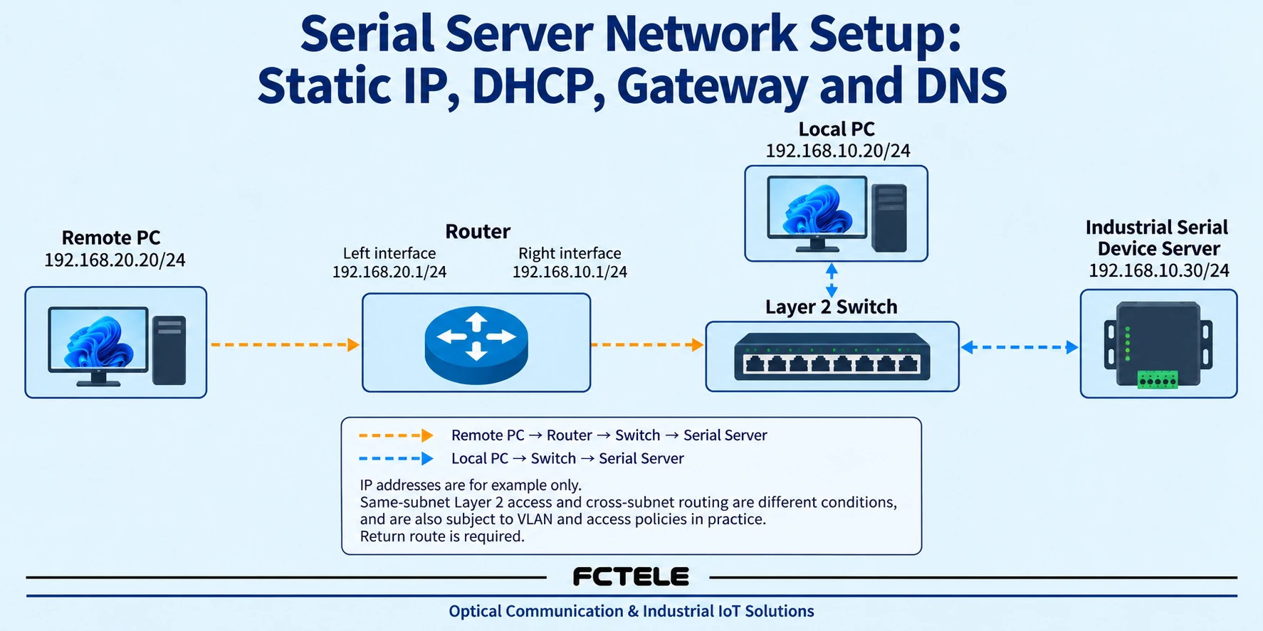
When a computer has multiple interfaces such as wired, wireless and VPN, access may go out the wrong network card. First record the interface, address and route actually used, rather than assuming that test traffic must start from here just because the network cable is plugged in. Do not casually set two network cards to overlapping subnets; and do not bridge the test computer and the production network without approval just to find a device.
3. How to choose between static IP and DHCP
A static IP is planned by the administrator and then manually written into the device. It is easy to hand over when the host computer accesses it at a fixed address, but the address should be unique and coordinated with the DHCP address pool; you cannot conclude that an address is unused just because one Ping gets no response. The device may have Ping disabled or be temporarily offline. Keep address allocation records and device identifiers to avoid two devices mistakenly using the same address and causing intermittent disconnections.
DHCP is the Dynamic Host Configuration Protocol. The client requests an address and related network parameters from the service. The common initial allocation process is Discover, Offer, Request, ACK: looking for a service, receiving candidate configurations, requesting the selected configuration, and getting confirmation. This process does not require an Internet connection, but the current network must have a reachable DHCP service; across subnets, a relay may be configured by the administrator. The lease has a time limit, and the device also needs to renew it according to the rules; you cannot treat one address acquisition as permanent.
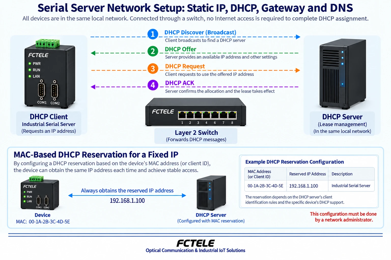
When centralized management is needed and the host computer needs a stable access address, DHCP reservation can be evaluated: the administrator reserves an address for the corresponding client, rather than arbitrarily setting an address within the pool on the device. The reservation may be based on the client identifier or MAC, and must be checked according to the server rules. It can only be used if the specific model supports DHCP; when the network has no DHCP, you should not guess that the device will fall back to some fixed address, but should check the manual and current status.
4. When DNS is needed
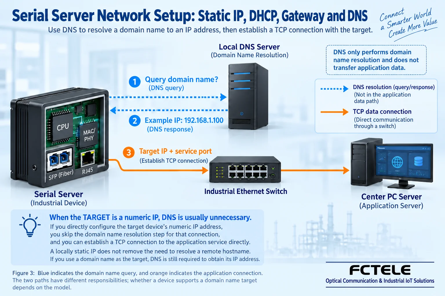
DNS is the Domain Name System, which converts name queries into corresponding records. When a device actively connects to a “collection center domain name,” it usually first queries the configured DNS service, and then establishes the application connection according to the obtained address. Successful resolution does not mean the TCP port is open; the DNS service is also not a relay station that all application data must pass through. When using a numeric IP as the target, domain name resolution is usually not needed for that connection.
Domain names and IPs are not strictly one-to-one: one name may return multiple addresses, and different names may also point to the same address. Records also have a cache validity period, so after changing resolution, not all clients will immediately use the new value. An internal collection center name may require the enterprise’s internal DNS, and casually switching to a public DNS may not resolve it. Which DNS address to use should follow the network administrator’s plan; you cannot treat the router address as a DNS service without confirmation.
5. Change the address safely and avoid locking yourself out
Before starting, save the model, firmware, current IP, address acquisition method, management entry point, application ports and host computer mapping, export the configuration and arrange a maintenance window. Menu names, initial accounts and application setting methods vary by product; this article does not provide universal default passwords or assumed menu paths. After the first login, set independent credentials according to the security policy. For firmware upgrades, confirm the compatible version, backup and rollback method, and do not update production equipment directly just because it is “the latest.”
First plan the new address and how the computer will reach it, then modify a single network parameter group. After saving, the management session may be interrupted simply because the address changed, not necessarily because the device is broken. Access again using the new address, and if necessary configure the test computer to an approved subnet. Whether settings apply immediately, require reconnection or require a restart depends on the model prompts. Do not change the IP, serial format and application mode at the same time, otherwise it will be difficult to distinguish the cause after a failure.
If you forget the address, first check handover records, DHCP leases, switch learning records or the manufacturer’s discovery tool. The broadcast of a discovery tool may not cross routes; not finding it does not mean the device is offline. Restoring factory settings will clear parameters and should be used as a last resort with authorization and backup; do not repeatedly press reset on a running bus. Management and application entry points should restrict access sources; for cross-public-network access, use approved secure access and do not directly expose control ports.
6. Acceptance by three layers of results
The first layer checks the network and management: link status, address conflicts, mask, routing and access rules are correct, and authorized computers can access the management entry point. Ping is only auxiliary evidence, and policies may prohibit it; a successful Ping also cannot prove that the application is connected. The second layer checks the application connection: confirm whether it is Server listening or Client actively connecting, the target IP or domain name, port and session status. When the domain name fails but the numeric address succeeds, check DNS separately and do not change serial parameters.
The third layer checks the real serial response: use read-only requests allowed by the device manual, and check the sent bytes, received bytes and return values. If the connection is established but there is no response, continue checking wiring, serial format, station number and protocol. Transparent transmission does not automatically convert Modbus RTU to Modbus TCP; only devices that support the corresponding gateway mode can convert according to configuration. Then test the expected load, reconnection and recovery after device restart. Any production interruption must be authorized.
The Feichang Technology serial server category and the FCT-1500 series 2855 details list multiple serial ports and combinations of electrical and optical ports, allowing model selection by interface count and deployment medium; the network protocol column in that detail lists DHCP/DNS, and also lists WEB management, cross-route communication and automatic reconnection, which can be used to check address allocation, centralized configuration and recovery requirements. However, supporting these functions does not mean that on-site routing and DNS are already correct, nor does it guarantee that every reconnection preserves application state. Optical ports cannot replace correct IP and routing configuration. Specific ordering models, firmware, menus and recovery conditions still need to be checked in the manual, and cannot be inferred from the interface appearance. For complete access steps, see Usage Tutorial , and for byte and loopback verification see Configuration and Debugging Guide .
References: IETF RFC 2131 (DHCP) ; IETF RFC 1034 (DNS) ; Feichang Technology Serial Server Category ; 2855 Product Details . The schematic diagrams are illustrations of general mechanisms and do not represent actual products or measured parameters. The example addresses cannot be used directly for production configuration.
How dynamic domain names handle address changes
DDNS is Dynamic DNS update, which lets a name record update as the target address changes; it is two different actions from a device querying DNS. The update is performed by a router, host or client that supports the corresponding mechanism. If a serial server only has domain name query capability, you cannot assume from this that it can publish updates by itself. The update interfaces of commercial services may also differ, and the menu of some old tool cannot be treated as a unified protocol.
After the address changes, you also need to consider DNS caching, record validity period and when the device re-resolves. An already established TCP connection will not automatically migrate to the new address just because a resolution record is changed. When the device uses TCP Client to connect to the center, first confirm that it allows entering a domain name, configuring DNS and the center application port, then observe the re-resolution and reconnection results; verify the specific trigger conditions according to the model. A domain name does not eliminate NAT, firewall or carrier shared address restrictions, and DDNS cannot replace secure network access.
In a controlled environment, change the target record, check the query result, the actual connection address and application readings, and record the old connection release and recovery behavior. Do not directly open public network control ports for testing. Reference RFC 2136 Dynamic Update Mechanism ; whether the service provider’s update method is consistent with this mechanism needs to be checked separately.
This article carries over the valid content of the corresponding old article. The schematic diagrams are general principle illustrations; general mechanisms and specific model capabilities should be checked separately.
Translated from the Chinese technical article. Source first published: 2022-12-06. Source last revised: 2026-10-13T11:01:30+08:00. Read the Chinese source
