


First, distinguish encoding from transmission
SRT is a protocol and software implementation for network data transmission. Audio and video devices commonly use it to send already-encoded data to a remote end. Camera capture, audio and video compression, network transmission, and decoding display are different stages: SRT mainly solves how data is delivered along the network path. It does not, by merely enabling one option, turn an HDMI signal into compressed video, nor does it determine the camera’s resolution. Before use, first confirm that both the sending software and the receiving device explicitly support SRT.
You can think of the encoder as the device that produces data, the transmission protocol as responsible for organizing that data to travel across the network, and the decoder as restoring the received content into sound and images. This only helps distinguish responsibilities; data in the network still has clear packet, numbering, and timing requirements. Even if an ordinary Ethernet switch can forward the relevant IP packets, it does not thereby become an SRT encoder or decoder.
If a packet is lost, how is it recovered?
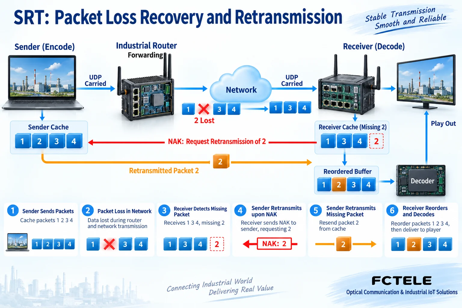
SRT adds the mechanisms needed for reliable transmission on top of UDP. The sender temporarily stores recently sent data. The receiver identifies gaps based on packet sequence numbers. When it finds that a packet has not arrived, it requests retransmission through feedback. The sender can send it again only if it still holds that data and the sending conditions are met. This process of resending based on feedback is called Automatic Repeat Request, often written as ARQ. It is a separate matter from video compression algorithms.
For example, if the receiver first sees packets 1, 3, and 4, it cannot assume from the sequence gap alone that packet 2 is permanently lost, because the network may also deliver packets out of order. The protocol handles gaps, feedback, and arrival status according to its implementation, and the receive buffer provides the conditions for in-order delivery. If the retransmitted packet 2 arrives in time, there is a chance to fill the gap; if the original data is no longer in the send buffer, bandwidth is insufficient, or recovery takes too long, retransmission may still fail. Reliable transmission must not be described as never losing packets on any link.
Why does recovering data require buffering?
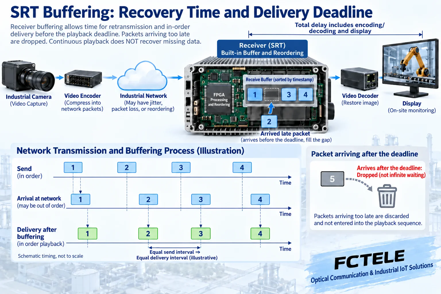
Real-time playback cannot wait indefinitely for one lost data packet. The receiver needs a period of buffer time to absorb variations in arrival time and to give feedback and retransmission a chance. SRT’s timestamp delivery mechanism schedules delivery to the application according to send timing, so even early-arriving packets may wait in the buffer. Buffering is not an algorithm that automatically repairs the picture; it trades a certain amount of waiting for room for data recovery and stable pacing.
Round-trip time means the time for a request to go and return, usually written as RTT; it is different from one-way network latency. Path distance, congestion, and wireless access all affect recovery opportunities. If the buffer is set too small, retransmission may not arrive in time; if it is set larger, it also increases waiting. A configured delay option cannot be directly treated as the total latency from lens to screen, because capture, encoding, decoding, and display each take time. The actual service link should be measured; do not claim that a fixed millisecond value suits every site.
Connection roles are not the same as data direction
A Caller usually actively initiates a connection to the other party, while a Listener waits for a connection at a specified address and port; Rendezvous is a mode in which both parties establish a connection together in a corresponding way. These describe roles in connection establishment. They do not mean that the Caller must be the video sender, nor that the Listener must be the receiver. After determining who actively connects, you must also check which end actually provides the audio and video and how the other end receives and decodes it.
Network Address Translation (NAT), firewalls, and port mapping affect whether a connection is reachable. Rendezvous helps with traversal in some environments, but it does not guarantee bypassing all network policies. The UDP ports used by the connection should be allowed according to the actual configuration, opening only the range required by the project; example ports must not be treated as the protocol’s only fixed ports, nor should all ports be left open long-term for troubleshooting. Differences in versions, stream identifiers, and device implementations should also be checked item by item.
Check encryption and service compatibility separately
SRT implementations provide encryption-related options, and devices need to support the corresponding functions and be configured with matching parameters. Key length, passphrase, and receiving policy should be checked against both parties’ versions. You cannot assume that every connection has encryption enabled just because the protocol name carries a security connotation. Mismatched settings may cause connection or data reception failure; passphrases should also not be disclosed in troubleshooting records.
Encryption protects data in transit; it does not replace device management permissions, network access control, or encoding compatibility checks. A connection may be established but still fail to play if the encapsulation method, video encoding, audio track, or receiving application is not supported. During verification, separately confirm session status, actual data arrival, whether decoding succeeds, and whether the picture and sound are correct. Do not look only at the green connection indicator in the software.
Which part can an industrial switch handle?
In Feichang Technology’s industrial switch product categories, the managed four-fiber eight-copper Layer 3 switch numbered 2241 lists VLAN, QoS, and related network management functions. Such a device can serve as a network node in an audio and video IP link, used to organize service paths, isolation scope, and forwarding priority according to the project; whether Layer 3 forwarding, optical ports, and specific port speeds are needed should be checked against the delivered model and the existing network.
This switch documentation cannot serve as proof of built-in SRT encoding or decoding capability. Endpoints still need to support the corresponding software and formats, and retransmission also consumes network resources. QoS can affect queuing priority; it cannot create egress capacity out of nothing. Fiber can extend the physical link, but it will not eliminate encoding delay. Selection should simultaneously list multiple streams, retransmission margin, service priority, and recovery requirements, rather than simply purchasing a higher nominal rate.
Verify the complete link, not just once
First confirm the same set of encoding, connection, and receiving parameters in a controlled network, then connect to the formal path. Record statistics related to effective data bitrate, path RTT, packet loss, retransmission, and receive buffering, and observe quiet and motion scenes, single-stream and multi-stream concurrency. When testing packet loss or path changes, use an isolated environment or an approved maintenance window; do not deliberately create congestion on a production control network.
If the picture is interrupted, first distinguish network disconnection, data recovery timeout, and decoding failure, then check the endpoint, address and port, bandwidth, and encoding format separately. When adjusting, change only one key condition at a time, and record the actual total latency and recovery result. Finally, save both parties’ versions, connection roles, data direction, buffer settings, encryption status, and test conditions, so that problems can be reproduced and delivery acceptance can be carried out.
Documentation note: The principle diagrams are used to explain general mechanisms; they are not product photos or measured records. Specific interfaces, modes, and capabilities are subject to the selected model, version, and on-site verification.
Verification materials: Haivision SRT project and ARQ mechanism
SRT timestamp delivery and delay mechanism
SRT tool connection modes and parameters
SRT socket options and encryption settings
Haivision SRT application Q&A
Feichang Technology managed four-fiber eight-copper Layer 3 switch
Feichang Technology industrial switch categories
Related technical topics: How to calculate audio and video bitrate: sampled data, compression peaks, and network capacity
Translated from the Chinese technical article. Source first published: 2022-01-18. Source last revised: 2026-10-13. Read the Chinese source
