


Start with the conclusion
First make an end-to-end requirements table, and avoid choosing a model by its housing
A serial fiber converter is used to extend compatible serial services to the other end of a fiber. For purchasing, first list the controller and terminal models, interfaces and messages, independent channels, fiber cable, power supply, environment and allowed collection cycle. The same housing may have different optical configurations and interface modes, and a similar name does not prove that one can replace another.
Industrial grade often involves installation, power supply, environment and electromagnetic compatibility design. It is not a unified promise of waterproofing, explosion protection or absolute lightning protection. Write the task you want to complete as testable conditions, then compare them with the specific order model and manual. This can avoid piecing together the best parameters of several versions into a device that does not exist.
Check the serial standard, control signals and number of channels together
RS232 three-wire data does not necessarily include handshake signals such as RTS and CTS. RS422 commonly uses independent transmit and receive differential pairs, while two-wire RS485 commonly shares a pair in time division. Terminals, references and modes all need to correspond; do not look only at the DB9 shape or the green wiring port. A full-signal requirement cannot be unconditionally replaced by a three-wire version.
Providing three types of interfaces may mean selectable modes, not that three independent devices can be connected at the same time. Record the remote channel, standard and configuration corresponding to each local channel. Cross-standard functions require clear model support, and the service messages on both sides must already be compatible; electrical crossover cannot replace protocol translation.
Character conditions and direction switching must be proven with real messages
Check the baud rate, data bits, parity, stop bits, flow control and continuous transmission conditions. If the page overview, table and customized functions are inconsistent, ask the supplier to clarify the current order, and do not choose the highest number yourself. Automatic recognition also has a range; do not assume from advertising that all parameters need no setting.
After two-wire RS485 finishes sending a complete set of data, it must release the line for the other side to reply. Releasing too early may cut off the tail, and releasing too late may block the response. Test the longest request, shortest response, representative load and continuous polling, and record head and tail integrity, parity errors and timeouts. Looking only at the transmit light will not reveal all direction problems.
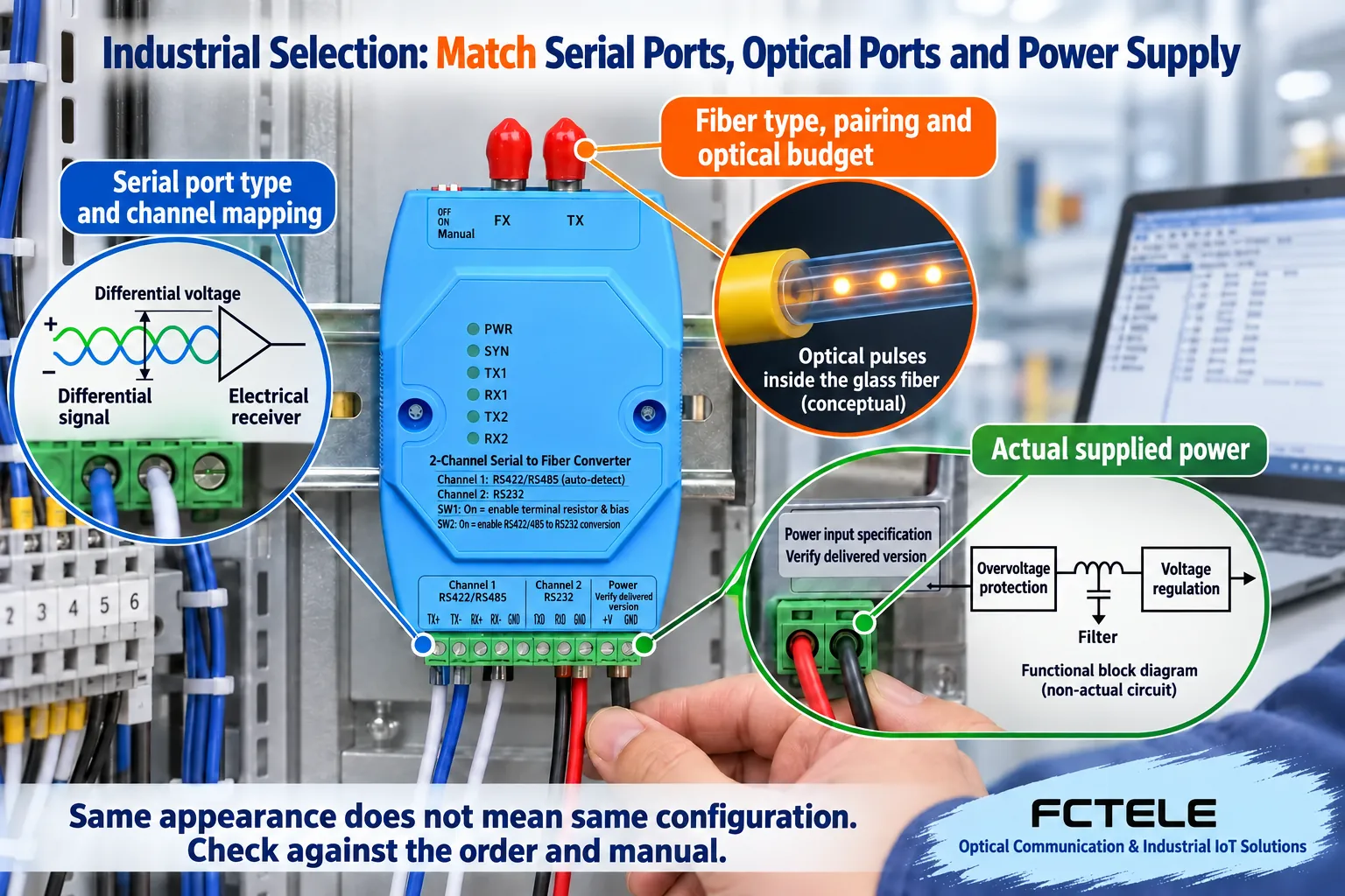
Optical configurations need to be paired, not just plugged in at both ends
Confirm single-mode or multimode, single-fiber or dual-fiber, transmit and receive wavelengths, connectors and end faces. For dual-fiber, TX usually connects to the opposite end RX; for single-fiber bidirectional, pair according to the corresponding optical combination. SC, FC, ST and LC are connection forms, and you cannot infer the optical wavelength, serial speed or service compatibility from them.
The optical port may also carry serial-specific transmission or Ethernet. These two types cannot be directly connected just because the connectors look similar. Provide two matched devices and versions that have been checked, write down the fiber core number and end face, and confirm replacement and repair according to the same pairing conditions, to avoid replacing only with a machine that has a similar housing.
The optical budget looks at both the weakest receive power and excessive input
Use the corresponding transmit power, allowed receive range and line loss to judge whether there is enough margin. Fiber cores, connectors, splices, bends and contamination can all consume optical energy. Kilometers are only a screening condition; do not mix the longest distance, minimum loss and another version’s sensitivity.
For a high-power long-distance version connected to a short fiber, you still need to check receive overload. Do not assume that higher power is always more stable, and the measuring instrument must also match the wavelength and conditions. First check and clean the end face, then measure according to the delivered specifications and keep the budget; do not look directly into the optical port, and do not test high power by yourself without the proper conditions.
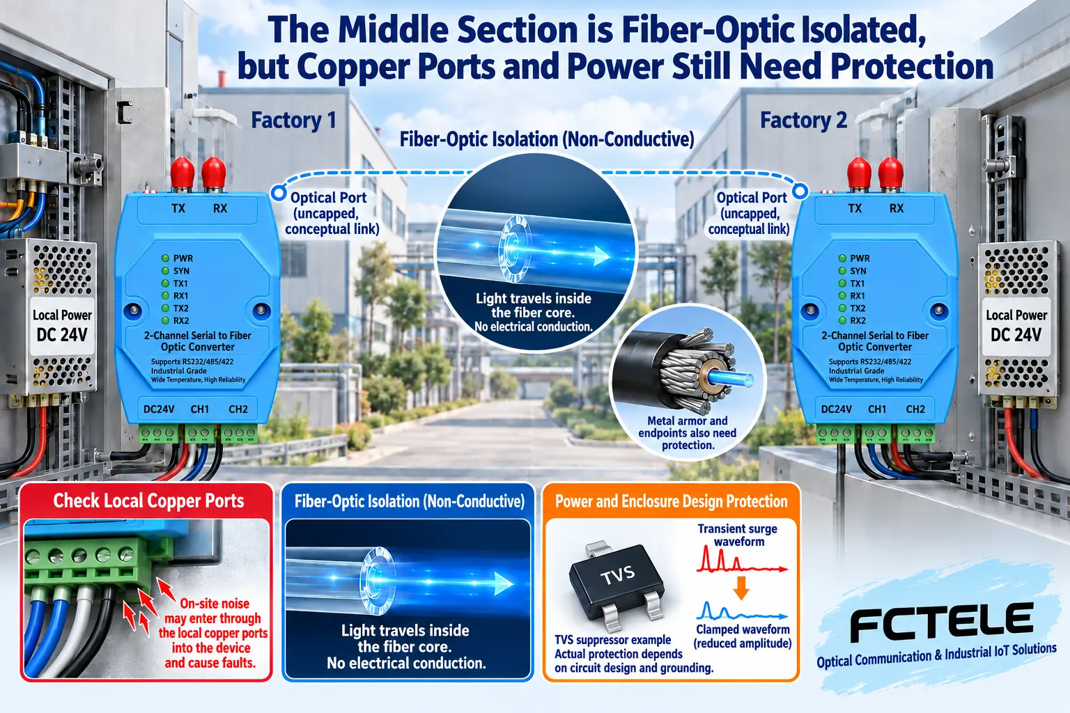
Power supply and local protection do not disappear along with the glass fiber core
A fiber data section does not automatically supply power to the remote device; both ends each need a suitable power supply. In the order, write the input type, range, polarity, connection terminals and power consumption. Also observe long-line voltage drop and power-up status. Wide voltage does not mean there is isolation, redundancy, reverse connection protection or all protection functions.
A glass fiber core does not transmit data through a conductive path, but copper ports, power supplies, enclosures and metal parts of the fiber cable are still on site. Check by model whether the serial port and power supply are internally isolated. Surge capability also involves test waveforms, impedance and installation. Do not omit endpoint protection or claim that the whole system has absolute lightning protection just because fiber is used.
Check environment, installation and maintenance space separately
The temperature inside a sealed cabinet may be higher than outdoors. Sunlight, nearby heat sources, ventilation and condensation can affect operation. Operating and storage conditions are different, and a housing rating does not prove suitability for a hazardous area. Without the corresponding documents, do not treat wide temperature or a metal housing as waterproof or explosion-proof certification.
DIN rail, wall mounting and fixing should follow the manual. Cables should have strain relief, jumpers should not be pinched by the cabinet door, and there should be space for end-face inspection and plugging and unplugging. For redundant power supplies, check whether the two paths are independent. Two wires from the same power source cannot eliminate the risk of power failure. Installation conditions should be included in acceptance, rather than added after a fault occurs.
FCP-D2 channel functions, put into the order table
The Feichang FCP-D2 details separately list RS422/485 and three-wire RS232 channels, and support specified crossover and standalone interface conversion. For tasks where the electrical interfaces differ but the messages are compatible, these functions can be checked against the documents. Do not understand it as being able to mutually convert all proprietary protocols.
The order attachment should state the terminal, channel, mode, parameters, optical pairing, power supply, installation and acceptance. For undetermined speed, environment or protection conditions, ask the supplier for the delivery basis, and do not replace it with full compatibility. When multiple channels or different topologies are actually needed, confirm the corresponding product rather than moving functions from another page.
From bench to site, keep reproducible results
First confirm that the original short copper-wire service is normal, then add the same pair of converters and a suitable short fiber, keep the terminal parameters unchanged, and check the channels and directions. Finally connect the formal fiber cable, and record power, messages, values and continuous polling. In this way, a bench failure and an on-site fiber cable abnormality have a comparable baseline.
Acceptance also checks representative load, link disconnection or restart recovery within the allowed window, and mechanical and electrical installation. Verify reading and command execution separately; retries must not cause unconfirmed repeated actions. Only when the delivered configuration, terminal table, channel table and normal data allow a later person to retest does it prove that the selection fits the actual task.
Documentation note: The illustrations are general mechanism diagrams and have been technically checked; the appearance marked with a model uses the official website photo as reference, and the other cutaway views and components do not represent the internal circuit of an actual Feichang product. They are not measured waveforms or real project sites. Wiring and power supply are subject to the delivered manual.
Verification materials: Feichang FCP-D2 two-channel serial fiber modem
FOA optical link budget
TI RS485 design guide
Translated from the Chinese technical article. Source first published: 2022-01-12. Source last revised: 2026-10-13. Read the Chinese source
