


The optical module inside a video optical transceiver is responsible for electrical-to-optical and optical-to-electrical conversion, but it usually does not directly turn the camera’s analog video into light. The device mainboard first samples, organizes, and encodes the service, then hands the electrical data suitable for line transmission to the optical component. When selecting an internal module, you must check the mainboard electrical interface, line encoding, rate, and optical path; on-site users should prioritize replacing the entire compatible part according to the manufacturer’s instructions, not look for substitutes based on appearance.
1. First distinguish video input from module input
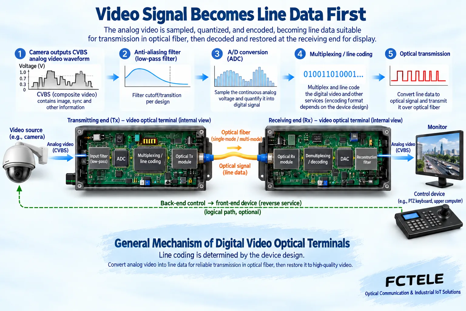
Take CVBS analog video as an example. The camera outputs a continuously changing voltage that contains the picture and synchronization information. The video optical transceiver first uses filtering and sampling circuits to turn it into a digital sequence, then organizes it together with other services supported by the device into line data. The receiving end performs the reverse process, restoring the video to the signal needed by the monitoring equipment. The optical module is usually located in the middle transmission section, not directly connected to the camera’s BNC port.
SDI digital video and Ethernet video are two other types of objects. Their external interfaces, line rates, and service processing are different, and you cannot apply an analog video optical transceiver design to them. The fact that the device internally transmits digitally does not mean the external video interface is SDI, and it certainly does not mean all video can be directly connected to an ordinary Ethernet SFP. Selection first determines the actual service, not just asking “how many channels of high definition.”
2. How sampling determines the amount of data to be carried
Sampling is like recording the voltage level at fixed time intervals, while quantization represents which interval the voltage falls into as a number. Before sampling, appropriate filtering limits the input frequency band to reduce aliasing caused by high-frequency components that do not meet sampling conditions. The sampling frequency and number of quantization bits are related to the required picture quality, but the final parameters must be determined by the design requirements and cannot be directly copied from fixed values in old articles.
A purely computational example can help understand the data volume: if a signal is recorded ten million times per second and each time is represented by ten bits, the raw sample data is one hundred million bits per second. This example is not a product specification and does not include frame structure, control information, or line coding overhead. Multiple services also need multiplexing, and the actual line rate must be calculated from the complete design. You cannot treat “how many megabits per channel” as a universal conclusion for all video optical transceivers.
3. Why low-speed control cannot be casually connected to the module
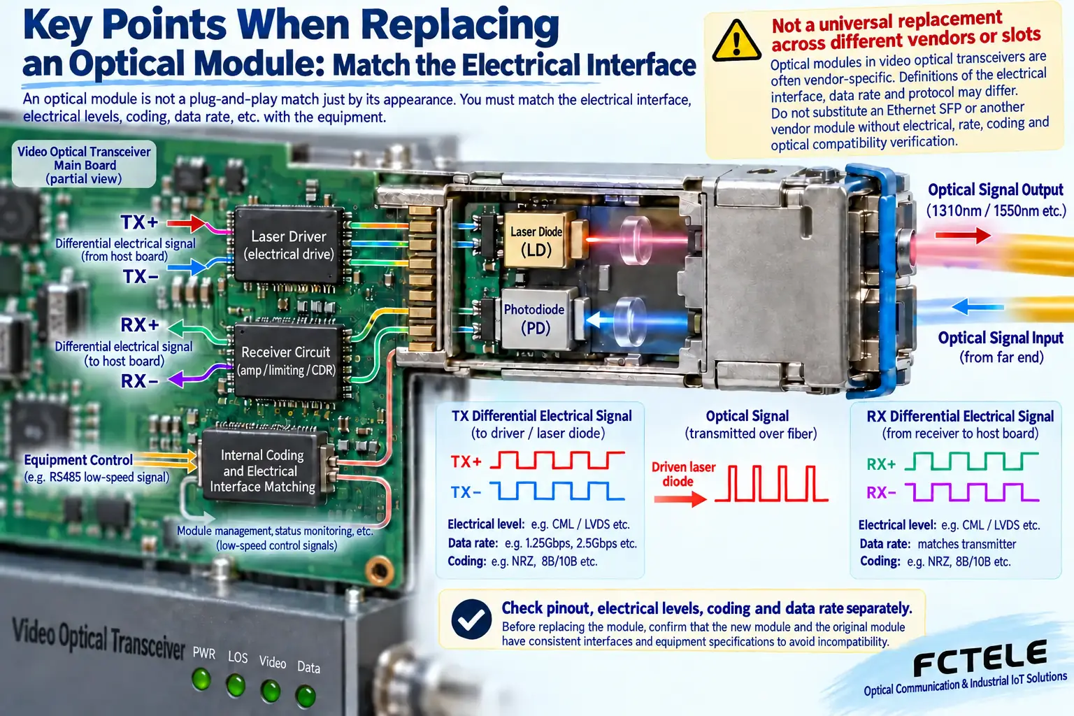
RS485 control service may have only a low data rate, but high-speed optical components cannot necessarily directly transmit arbitrarily slow changing levels. Some receiving structures, coupling methods, and clock processing need to meet specified line rates and data characteristics. The device usually has the mainboard organize the control data into a line structure suitable for transmission, then hand it to the optical component; this is completely different from connecting the two RS485 wires directly to the high-speed pins of the optical module.
The video direction and control direction may also be opposite, for example, the picture is sent to the back end while back-end commands return to the front end. There may also be bidirectional control or multi-service combinations, determined by the device’s support relationship. When selecting a module, confirm how the whole device implements transmission, reception, and multiplexing. Do not assume that because a module has transmit and receive functions, the whole device already supports arbitrary bidirectional video, telephone, or serial port services.
4. Electrical interface matching is not just about matching the number of pins
The mainboard and module may use a differential high-speed electrical interface. Differential means two wires together represent one signal, and the receiver focuses on the voltage difference between them; it does not mean these pins are RS485. Pin definitions, level ranges, input/output directions, AC coupling requirements, and termination conditions all need to be checked against the documentation. Even if the package is the same and the electrical connection positions look identical, they may not be interchangeable.
Clock recovery, decision, and line coding must also correspond. Some functions are inside the module, some are on the mainboard, and you cannot assume all modules handle complete data processing. Whether the data rate output by the mainboard is within the module’s supported range and whether the encoded signal meets link requirements must be confirmed by engineering design and testing. On site, you should not try plugging in unfamiliar parts to find answers, and you must never rewire the mainboard’s high-speed pins while powered.
5. Optical path budget and service format are two thresholds
After the module electrical interface matches, you also need to check the transmit wavelength, receive range, fiber type, connector, and line loss. Dual-fiber requires cross transmit/receive, and single-fiber bidirectional requires paired complementary wavelengths. If the received optical power is too weak, the ability to correctly interpret the signal decreases; if it is too strong, it may exceed the allowed input range. The nominal transmission distance is not a guarantee for any on-site line; splices, end-face contamination, and bends can all increase loss.
Even if the optical power is normal, correct video may still be absent due to mismatch in mainboard encoding, rate, or device version. During inspection, separate “how much light arrived” from “whether the correct service can be recovered.” Do not use a reading on an optical power meter to prove the entire device is compatible; do not use one static picture being normal to prove that synchronization, dynamic pictures, and reverse control are all qualified. The acceptance object should be the complete service path.
6. How to understand the modular features of Feichang Technology video products
The Feichang Technology official website page for the four-channel digital video optical transceiver introduces multi-channel forward video transmission and auxiliary services provided according to configuration, and shows combination ideas such as desktop and rack-mount. Modularity can help organize equipment according to the number of services, but modular whole-device configuration here does not mean users can freely replace any internal optical module. Specific channels, directions, and optional services need to be confirmed according to the order configuration.
This type of equipment provides a fiber transmission section for analog video systems, and the mainboard handles the corresponding video processing and service organization. If the project still has CVBS cameras, check the video interface and control requirements; if it has been changed to network cameras, reselect equipment according to the network system instead of just replacing the internal optical component. Product features should be explained within a clear service context, and you cannot derive general protocol conversion capability from one model.
7. What design selection and on-site replacement each do
Equipment designers need to obtain the module’s electrical and optical data, evaluate it together with the mainboard design, and verify under specified temperature, load, and line conditions. Testing should include dynamic video, synchronization stability, auxiliary services, and error conditions, not just check whether the laser emits light. During mass production, version and supply consistency must also be confirmed; you cannot omit subsequent compatibility verification just because a prototype works.
On-site maintenance personnel should first confirm the whole device model, serial number, and matching relationship, record indicator status and service phenomena, then handle external wiring, power supply, and end-face cleaning according to manufacturer guidance. Internal repair should be left to capable personnel; do not disassemble the optical component to adjust the laser or directly look into the optical output port. When replacement is needed, ask the manufacturer for compatible parts and verification steps, keeping risks within a controllable range.
Reference materials:Feichang Technology four-channel digital video optical transceiver product details; Ethernet SFP specification materials, used to explain specific interface support boundaries rather than as a basis for video replacement. The illustrations are general mechanism diagrams, not actual product photos, schematics, or repair instructions.
Translated from the Chinese technical article. Source first published: 2020-01-08. Source last revised: 2026-10-13T13:28:52+08:00. Read the Chinese source
