


The fiber is already down, but the switch’s network port light is still on. Why? Because the switch may only see the short network cable between itself and the media converter, and does not yet know that the fiber in the middle is broken. FEF is responsible for notifying the far end of a optical receive fault; LFP is responsible for reflecting a link fault on one interface to an associated interface. They help devices see faults; they are not automatic repair functions.
1. First look at normal connection: why is it necessary to pass on faults?
This article discusses Ethernet fiber media converters and does not mix telephone, E1, or video equipment into the same category. Their basic job is to convert Ethernet electrical signals into optical signals, and at the other end convert them back into electrical signals. Switch A connects to media converter A through a network cable, the two media converters connect through fiber, and media converter B then connects to switch B through a network cable. Having power does not mean this complete path can communicate.
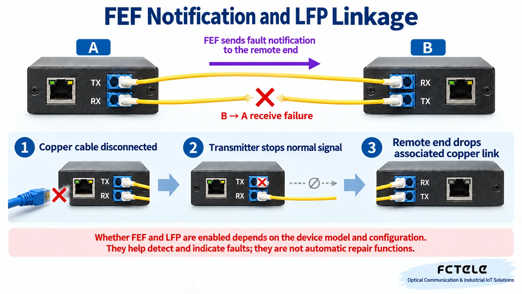
Figure 1 uses dual-fiber connection: TX is the transmit port, RX is the receive port. A’s TX connects to B’s RX, and B’s TX connects to A’s RX; the two fiber cores each handle one direction. If one of them is broken, it may happen that one end can still receive light while the other end cannot. The arrows in the figure indicate signal direction, not that the fiber itself can judge faults.
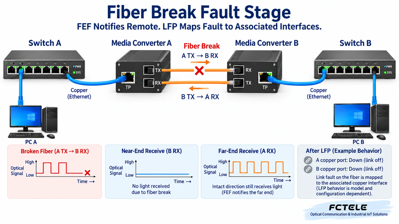
If the media converter’s electrical port and optical port each work independently, after the fiber in the middle is broken, the switches on both sides may still maintain connection with their local electrical ports. Therefore, “the network port light is on” and “end-to-end service is normal” are not consistent. What FEF and LFP solve is letting associated devices perceive a link abnormality; they do not check all application errors, and they cannot replace actual service testing.
2. What is FEF: telling the far end “I cannot receive”
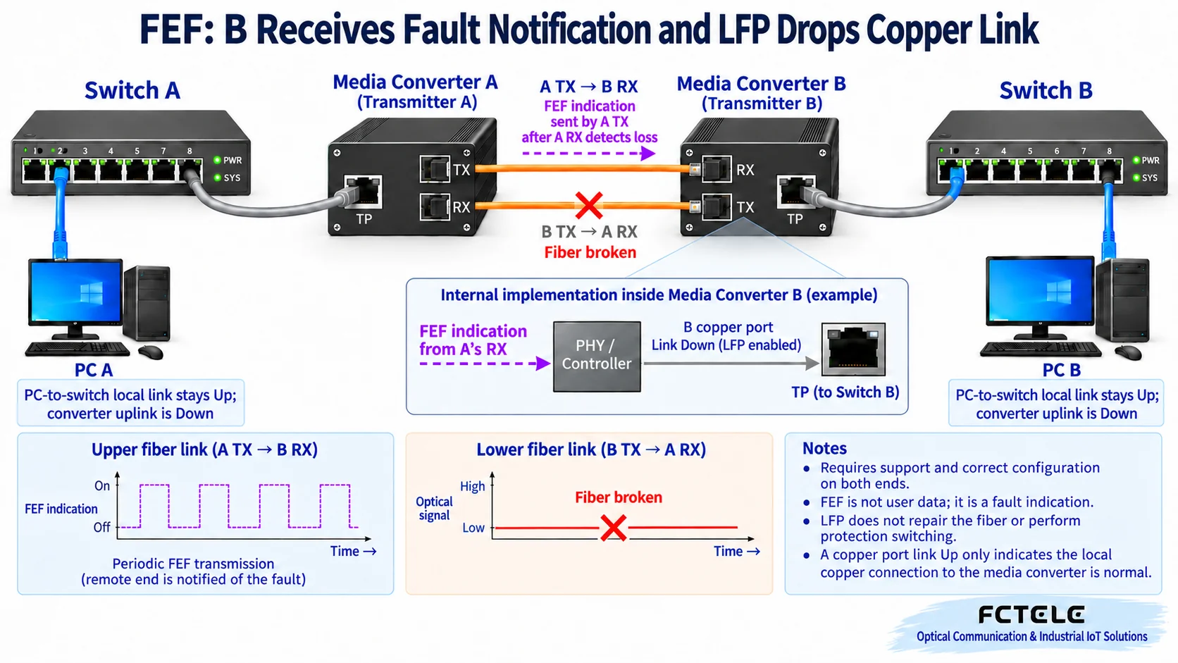
FEF is Far End Fault, usually translated as remote fault indication. Taking a 100BASE-FX 100 Mbps optical link that supports this mechanism as an example, when the local end’s optical reception fails, it can send a fault indication through its own still-working transmit direction, letting the far end know “the signal you sent, I can no longer receive.” It is not ordinary service data, nor is it sending a management alarm web page to the far end.
Note two boundaries: First, there must be a usable reverse channel for the notification to have a chance to arrive; if both fiber directions are broken, you cannot expect to send a message through the broken fiber. Second, whether the electrical port is shut down after receiving FEF depends on the device’s link linkage setting. Different rates and hardware may also use other remote fault mechanisms, and not all gigabit media converters can be treated as the same kind of 100 Mbps FEF implementation.
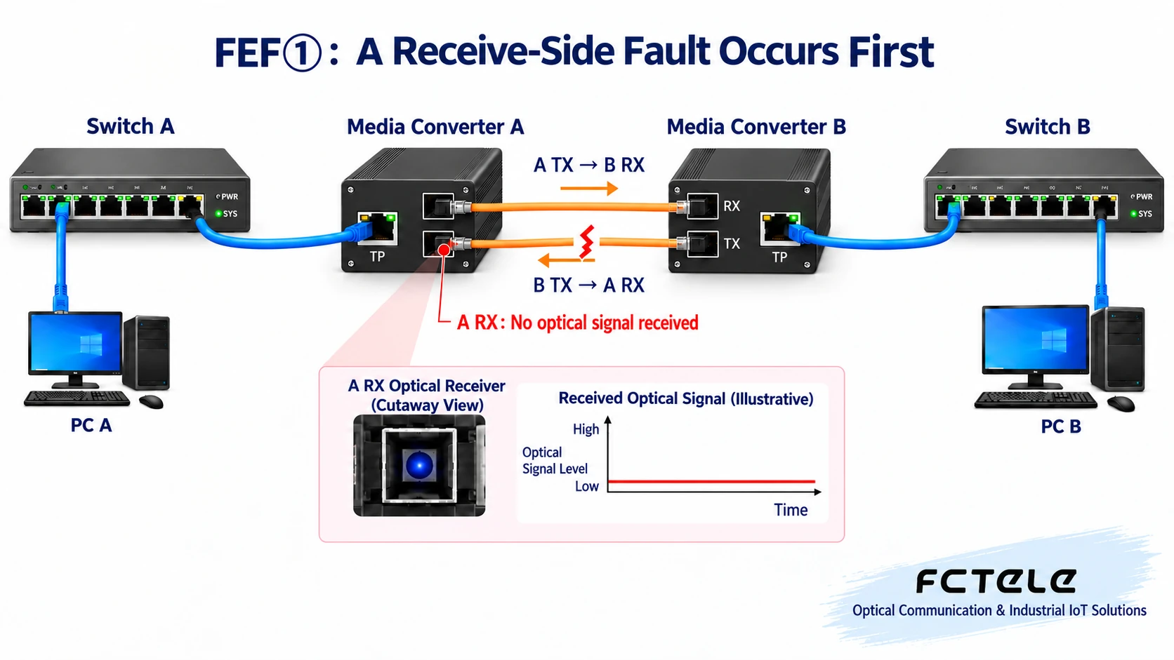
① A’s optical receive direction fails first
Assume the fiber from B to A is unplugged. A’s RX cannot receive a normal signal, and A first detects the reception abnormality locally. At this time, the other fiber from A to B is still intact; the fault occurred in one direction, and the figure should not be understood as the entire pair of fibers being broken.
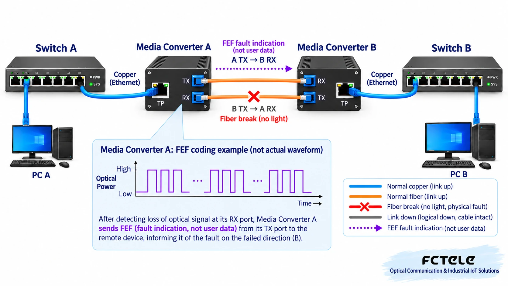
② A notifies B along the intact transmit direction
A sends an FEF indication in its own TX direction, which is received by B’s RX. That is, “the end that discovers the fault feeds back along the other direction.” If the notification arrow is drawn on the already-broken B-to-A fiber, then the working process is explained incorrectly.
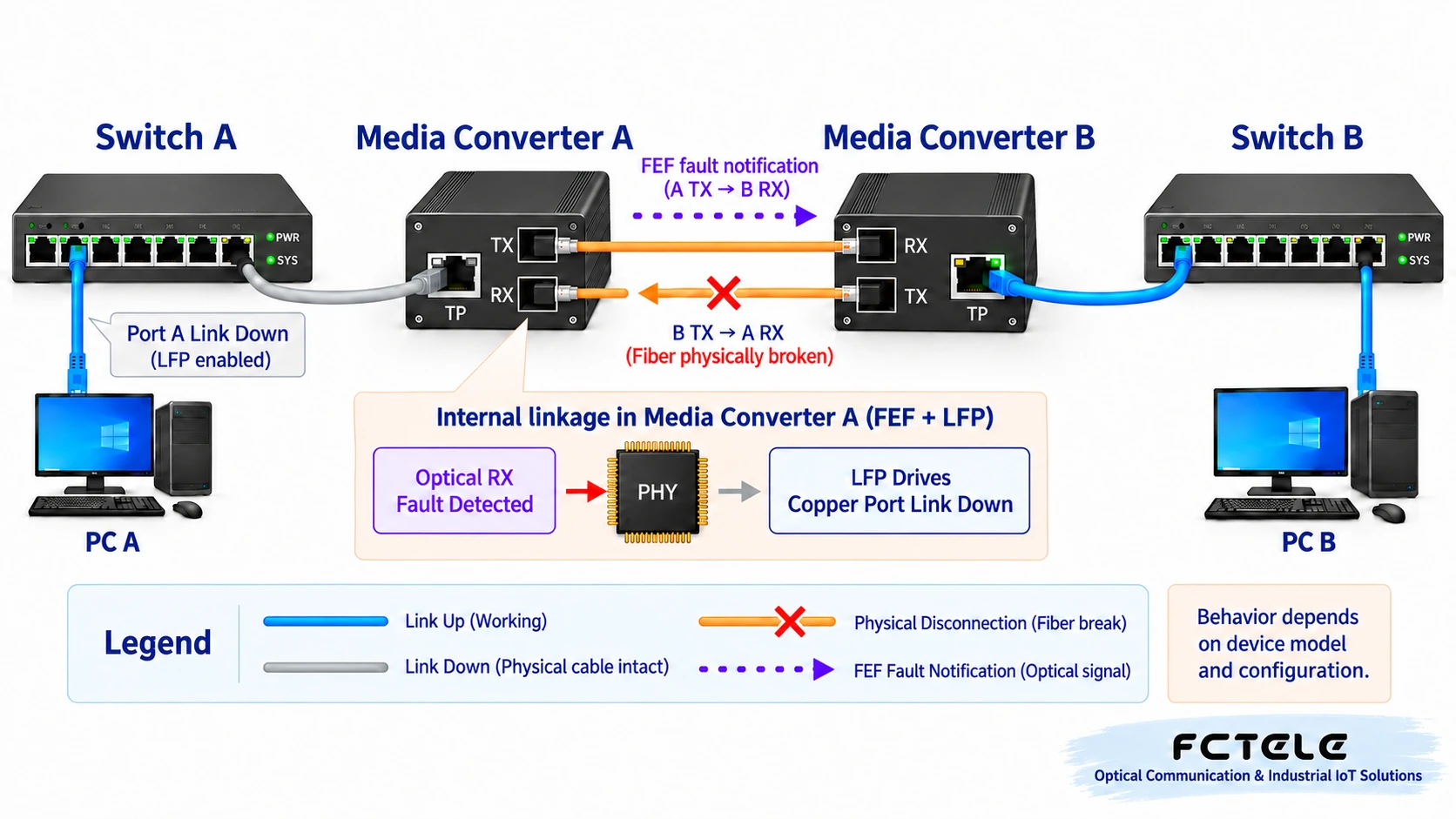
③ A reflects the local fault to the associated electrical port
To preserve the original linkage process, Figures 4 and 5 assume both ends support and have enabled the corresponding FEF and LFP functions. A can reflect the local optical receive fault to the electrical port, causing switch A to see the port connected to the media converter enter Link Down, meaning the physical link connection has failed. The network cable is not necessarily actually broken; the media converter may actively stop maintaining this link.
④ B receives the fault indication, then lets the right-side switch perceive it
B receives the remote indication and handles the associated electrical port according to configuration, letting switch B also see an abnormality on the media converter’s uplink port. Both sides can more easily identify failure of the complete path. Whether the switch records logs, sends management alarms, or switches to a backup link also depends on switch functions and network design, and cannot be automatically guaranteed by FEF. A computer connected to another port of the switch also does not necessarily need to be disconnected at the same time.
3. What is LFP: letting a fault not stay only at one interface
LFP is Link Fault Pass Through, which can be understood as link fault pass-through. Here, “pass-through” means reflecting the link failure state to another interface, not forwarding a copy of user data. A copper-side disconnection can cause optical-side linkage; an optical-side failure can also be reflected to the copper side. The specific association scope, detection conditions, and whether it needs to work with FEF must be checked in the model’s manual.
Below, the original three-step copper-side fault process is preserved, with both ends enabling the necessary linkage according to the manual. “Stopping normal signal transmission” is used to represent one implementation, and it is not written as an action uniformly used by all manufacturers. Actively making the associated link fail after detecting a fault is to prevent the other side from continuing to treat this path as available; it is not the media converter creating another physical disconnection.
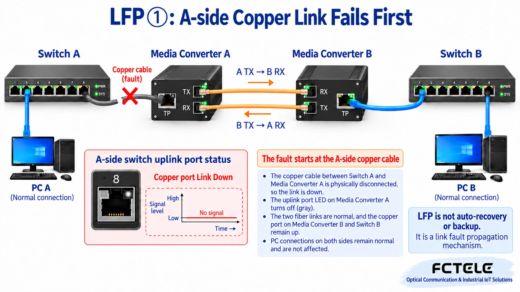
① A-side copper cable is disconnected first
Assume the network cable from switch A to media converter A is unplugged. A’s electrical port detects Link Down; the optical cable is still intact at this time. You must first distinguish whether the fault starts from the copper side or the optical side; otherwise it is easy to focus only on the optical port light when troubleshooting.
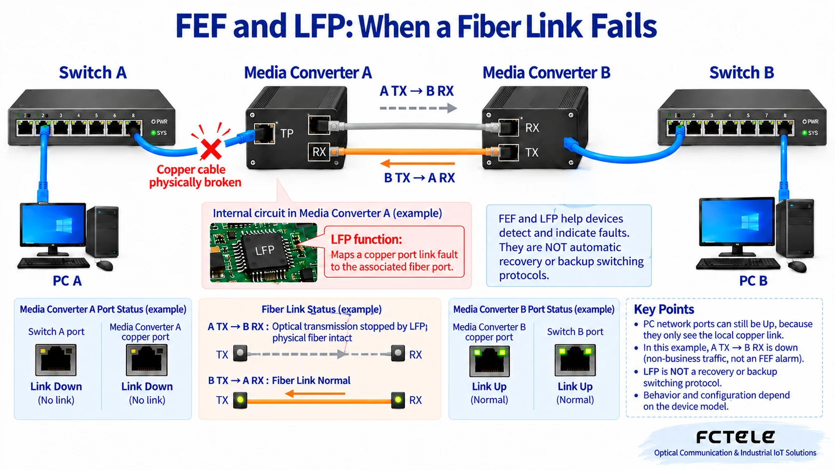
② A reflects the copper port fault to the optical port
A’s linkage control makes the corresponding optical-side link fail, so B detects a reception abnormality. The gray optical path in Figure 7 indicates that normal link signal transmission has stopped; the fiber itself is not broken. This differs from the explanation of FEF sending a specific indication through the intact direction. A specific product may combine remote fault mechanisms, and the internal implementation cannot be determined from just one gray arrow.
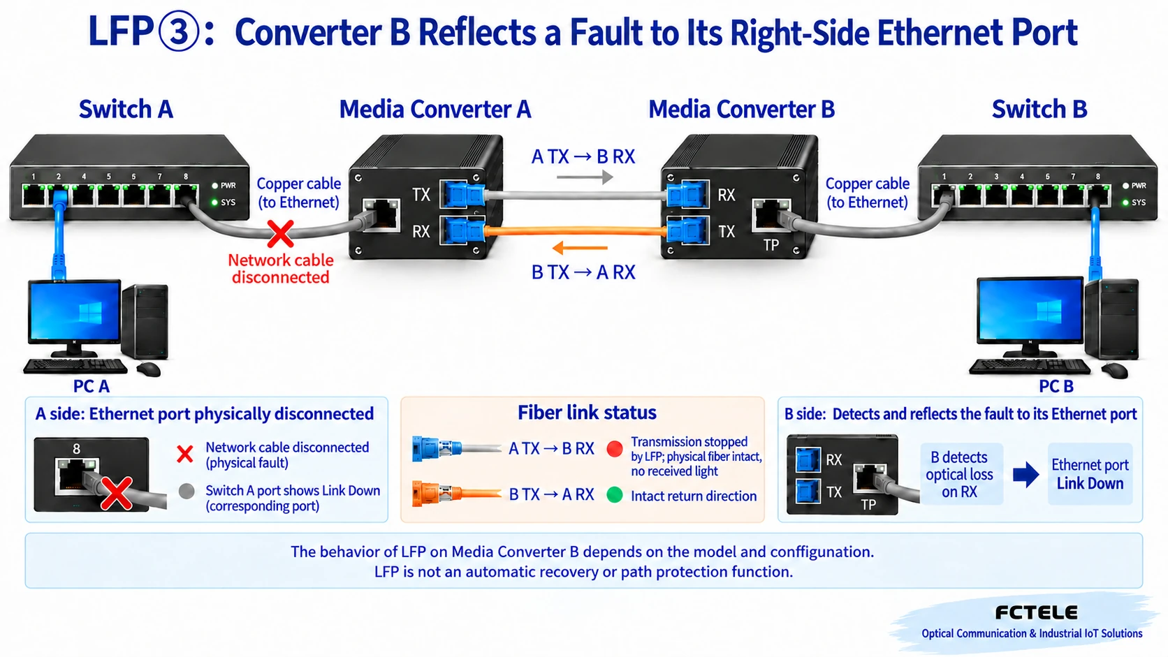
③ B reflects the optical-side abnormality to the right-side electrical port
After B discovers that the associated optical port has failed, it makes the electrical port connected to switch B enter Link Down. Thus the remote switch can also see that this uplink path is unavailable. Only if the network itself is configured with an effective backup path and switching mechanism can services possibly take another route; enabling LFP alone will not create a backup line out of thin air.
4. Putting the two processes together
FEF focuses on answering “how the receiving end tells the sending end”; LFP focuses on answering “how an interface fault is reflected to the adjacent device.” One leans toward remote notification, the other toward state linkage. They can work together, but they are not two names that replace each other. They should also not be confused with ring network protocols or optical backup switching.
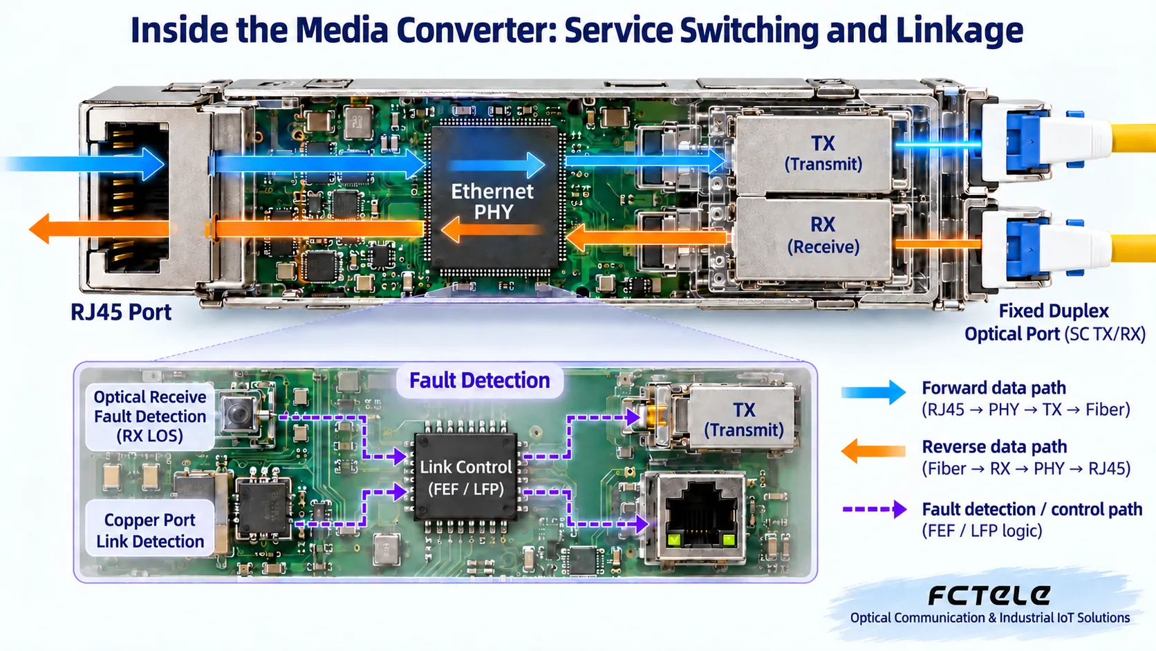
5. How to configure, troubleshoot, and accept?
First confirm the model, hardware version, optical port rate at both ends, single-mode or multimode, transmit/receive wavelength, single-fiber or dual-fiber, and optical power budget, then check the FEF and LFP support scope. Using paired devices from the same series is usually more convenient for checking, but “same brand” does not automatically prove that settings are compatible. DIP switch numbers also cannot be copied across models; whether changing settings requires a restart should be done according to that model’s manual.
The Feichang Technology official website product page for the “Gigabit 1-fiber 1-copper fiber media converter with LFP function” clearly states 1 optical port, 1 electrical port, optical port alarm transmission to the electrical port, and DIP-1 turning LFP on or off. This provides a selection basis for scenarios that need the switch to perceive optical-side faults. However, that page does not clearly state a model field, and it cannot be used to conclude that all versions have the same mechanism as the 100 Mbps FEF in this article; when ordering, the specific part number, linkage direction, and test conditions must still be confirmed.
Acceptance should be carried out in an approved test window. First record the normal state, then simulate only one fault at a time: separately disconnect one optical direction and disconnect one side’s copper cable, observe the associated ports of the media converters and switches at both ends, and after recovery check normal communication. Do not unplug both fibers at the same time to verify “feedback along the intact direction,” do not randomly break links in production, and do not look directly into optical ports. Record which port detects first, which port links, and whether services can recover; do not invent a uniform millisecond specification.
If all Link lights are normal but services still do not work, continue checking VLANs, IP addresses, application ports, and service data; these problems may not trigger FEF or LFP. Finally, remember: their value is to make link faults visible; repair still has to deal with the original disconnection or device problem, and reliable recovery also depends on correct network design.
References and figure notes
Figures 1–8 in this version were redrawn in the order of the original figures, and Figures 9–10 are new. All are general mechanism illustrations, not product photos, measured waveforms, or performance proof. The main text distinguishes between the FEF notification and electrical port linkage that were confused in the original text.
Translated from the Chinese technical article. Source first published: 2022-11-18. Source last revised: 2026-10-13T19:28:50+08:00. Read the Chinese source
