


A single E1 fiber optic modem extends one E1 digital service over fiber to a remote end. The nominal E1 rate is 2.048 Mbit/s. It is not ordinary Ethernet, and it is not a telephone interface that works just by plugging in a telephone. Whether service can pass must be checked by confirming the electrical interface, framing, clocking, and optical configuration at both ends at the same time.
1. E1 carries a continuous digital stream, not a network port speed name
E1 is commonly found in traditional leased lines, switching systems, and digital service access. It sends bits out in a continuous time sequence. The receiving end must not only recognize the data, but also know at what moment to judge the data. This rhythm is the clock. When a fiber optic modem extends the link, it must reliably recover the data and the required timing relationship, not merely let the other end see a string of light turning on and off.
Ethernet, by contrast, organizes transmission into frames, and ports can negotiate different physical rates. The interface rules of the two are different. Seeing an RJ45 shape on a device panel does not mean it can be plugged into a switch. The same connector may be used for different services, so the port label, pin definition, and manual must be read. Between E1 and a network, a conversion or encapsulation device supporting the corresponding function is needed.
2. What happens from electrical signal to optical signal
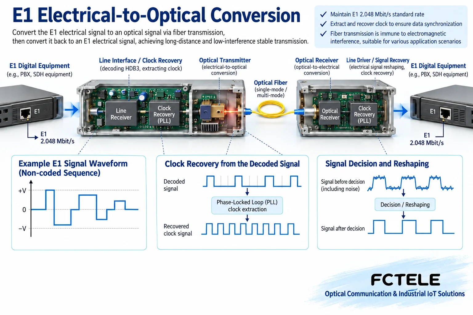
The E1 electrical port first uses line receiving circuitry to recognize the signal, recover bits according to the coding rules, and handle clocking. The optical transmit section converts the corresponding digital information into an optical signal. The remote detector converts the received light back into an electrical signal, and after recovery processing outputs an E1 line signal that meets the corresponding interface requirements.
HDB3 is a common E1 line code. Through specified pulse and substitution rules, it controls situations where the line has no change for a long time, making synchronous recovery easier. It is not three service types, and it does not equal “three times the bandwidth.” There is no need to memorize every coding pattern. First understand that a continuous digital stream needs a judgeable data level and a time reference.
3. Why 75 ohm and 120 ohm cannot be mixed casually
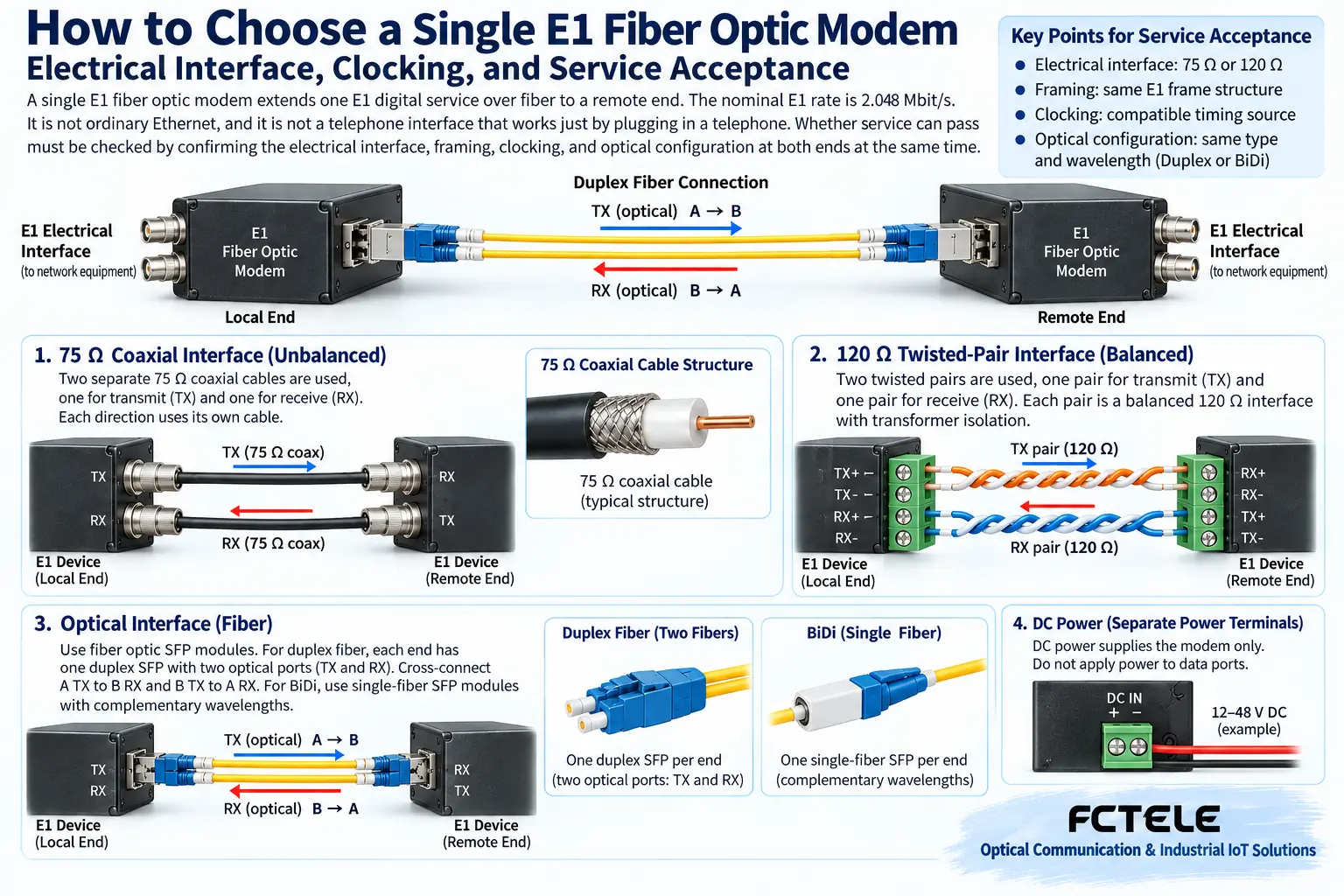
A 75 ohm unbalanced interface often uses coaxial cable; a 120 ohm balanced interface often uses twisted pair. Impedance describes the electrical conditions a signal faces as it propagates along a transmission line. It is not an ordinary DC resistance measured with a multimeter. If the line, connector, and port do not match, reflections will occur or receiving conditions will worsen.
A balanced interface carries information through the voltage difference between a pair of conductors; an unbalanced interface uses the corresponding signal conductor and a reference conductor. When conversion from one interface to another is needed, a suitable impedance conversion solution should be used, not just a different plastic plug. Transmit and receive must also be connected separately to the corresponding direction at the far end. The local transmit must not be connected to the far-end transmit.
4. Framed and unframed must be clarified
Framed E1 organizes frames and time slots according to regulations. A time slot can be understood as a position in a repeating timetable, but some positions may carry synchronization, signaling, or other duties, so not all positions can be counted as customer payload. Unframed mode usually carries the complete digital stream as a continuous service, and the far-end operating mode still needs to match.
Feichang Technology framed E1 fiber optic modem and unframed E1 fiber optic modem provide corresponding configuration choices respectively. They help users select models around the existing equipment mode; they are not interchangeable based on appearance alone. Framed time slots, clock mode, and ordered optical parameters should be confirmed at the same time.
These two FCP-E product details also list local and remote loopback and pseudorandom code test functions. Loopback returns the test signal along a specified path, helping to judge a certain link section; pseudorandom code is a test sequence with a known pattern, making it easier to check transmission errors. They can reduce blind cable swapping during commissioning, but testing occupies the corresponding service, so a maintenance window must be arranged, and the actual ordered version and operating instructions must be checked.
The so-called N×64 kbit/s often involves time slot usage in framed services or corresponding interface conversion. It cannot be directly understood as meaning that all single E1 fiber optic modems have a V.35 port. Additional Ethernet functions also need to be checked for how they are carried; an electrical port marked 10/100M does not mean that 100 Mbit/s of payload throughput can still be obtained after passing through E1.
5. Why clock mismatch may cause errors even when the light is on
Data needs to be sent and read at a suitable rhythm. The clock source may come from the local end, the E1 line, or a specific recovery method. If the two ends are configured unreasonably, the buffer may gradually accumulate or run out, causing slips or service abnormalities. The optical port still receiving light cannot rule out a clock problem.
During inspection, first save the configurations at both ends, then check how one end provides the clock, how the other end recovers the clock, and whether intermediate equipment forms an unreasonable dependency. Do not casually change parameters at both ends at the same time just to eliminate an alarm; otherwise, even if service is temporarily restored, it will be difficult to know the real cause. The specific design of the clock network should be completed by engineering personnel familiar with the service and based on equipment documentation.
6. A practical commissioning sequence
Assume two sets of E1 service equipment are several kilometers apart. First establish a baseline under short-fiber conditions using matched cables and known configurations. Record impedance, framing, coding, clocking, alarms, and service test results. The short fiber itself must also meet the receive power range; a strong optical port must not be connected directly to short fiber while ignoring overload risk.
After connecting the formal optical cable, check transmit light, receive light, the E1 electrical port, and end-to-end service separately. Receive power must be both above sensitivity and below the overload limit. A distance label cannot replace on-site loss calculation. Suitable loopback or bit error testing must be performed during a maintenance window to prevent test service from affecting production. Only after saving the real service operation record and configuration backup is commissioning complete.
Interface basis:ITU-T G.703. The figure is a general principle illustration and does not represent specific product wiring definitions, certifications, or measured data.
7. How to avoid mistaking symptoms for causes during troubleshooting
No received light, E1 loss of frame, and service failure to complete are phenomena at different layers. For no received light, first check the optical configuration, the line, and power at the far end; for E1 loss of frame, check the electrical port wiring, coding, and clocking; if service still does not pass, check the service configuration of the systems at both ends. Do not replace the entire link just because of one alarm. Known-good equipment or cables can help with cross-verification, but each replacement must be recorded, and a test loopback must not be left in the production line all the time. After solving the problem, the service conditions that originally caused the error should still be observed, rather than only checking that the panel has returned to normal.
Translated from the Chinese technical article. Source first published: 2019-10-08. Source last revised: 2026-10-13T18:52:49+08:00. Read the Chinese source
