


First distinguish: which problem does electrical isolation solve?
In a factory building, when a motor starts, monitoring occasionally goes offline, and equipment connected across buildings is also at risk of lightning damage, people think of using fiber. The value of a fiber optic transceiver or media converter is to change the long-distance communication section into optical transmission, reducing conductive and electromagnetic coupling problems on that section of the line. It cannot, merely by turning electrical signals into optical signals, stop hackers, separate two service networks, or guarantee that the entire system is immune to lightning damage.
Electrical isolation focuses on whether there is a direct conductive path between two circuits. Electromagnetic compatibility focuses on whether equipment can work normally when interfered with and whether it interferes with other equipment. Network isolation focuses on whether data can be forwarded across service boundaries. The three correspond respectively to current, interference, and data access. This article discusses the first two. Readers who need to separate a production network from an office network should also check the channel structure, switching and forwarding, and management interfaces. A section of fiber cable cannot be used as proof of network security.
How does data cross a section of non-conductive fiber?
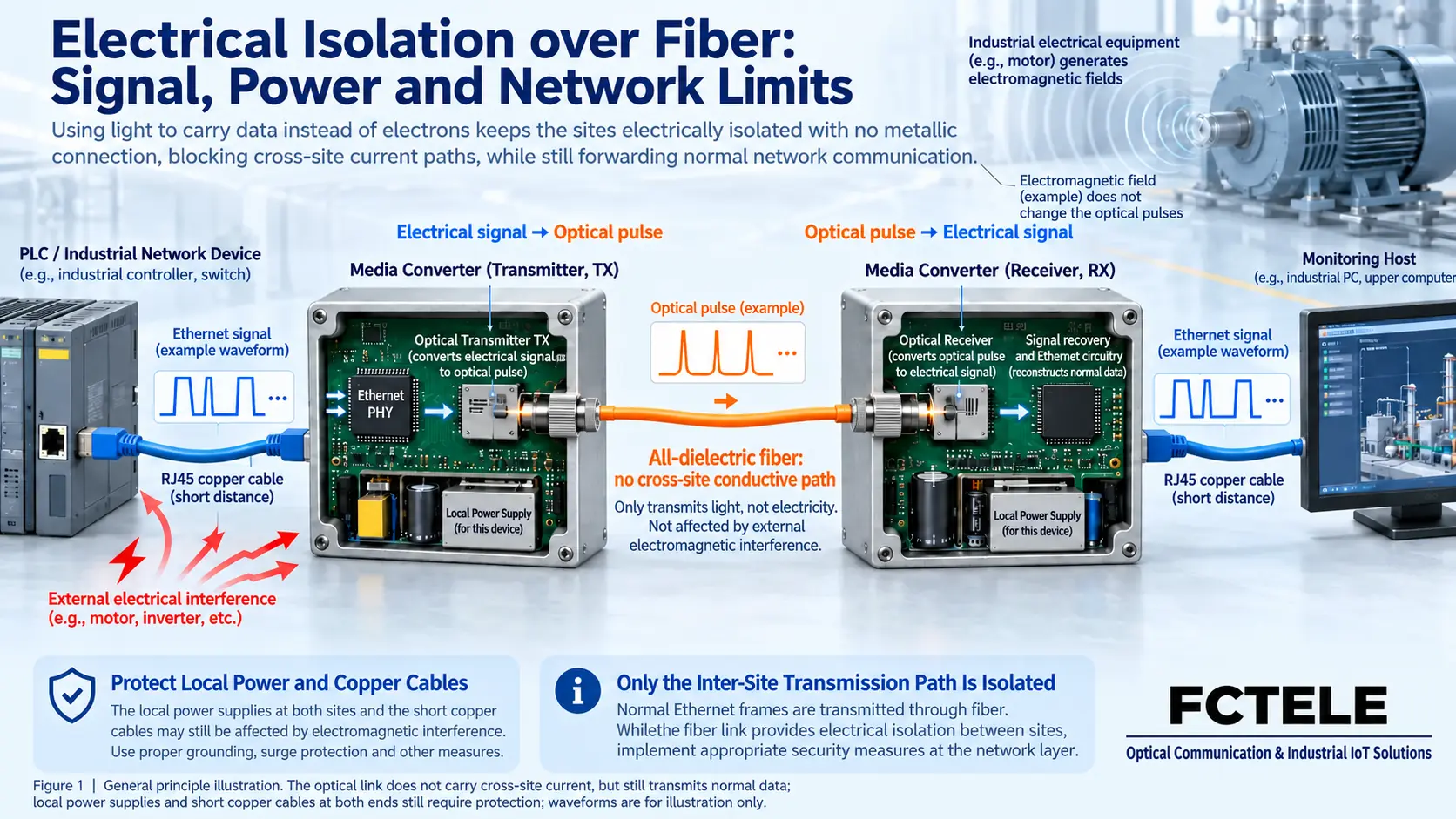
Take an ordinary Ethernet media converter as an example. The transmitting end first receives the signal on the short network cable, recovers the data through physical-layer circuits, and then uses an optical transmitter to encode the information into changes in light. Light propagates along a glass or plastic fiber core. The photodetector at the receiving end converts the received light into an electrical signal, which after receive processing is sent back to the Ethernet interface. Data continues to be transmitted, but the long-distance section does not need a copper conductor to carry current.
This process relies on the generation, propagation, and reception of light. It does not carry the remote voltage along the fiber. An ordinary non-metallic fiber communication section does not form a cross-site conductive path like a long copper line. The electronic devices at both ends still each need power and still contain electronic circuits. The figure shows only one direction. An actual bidirectional link must also complete matching at both ends according to the selected dual-fiber or single-fiber mode.
Why is fiber immune to interference, yet equipment can still go offline?
In industrial sites, inverters, relays, and motor switches generate interference. Electrical signals in copper cables may be affected by electromagnetic coupling. What is carried inside fiber is light, which reduces the sensitivity of that section of transmission medium to electromagnetic interference. Therefore, changing a long copper cable across factory buildings into an optical path can free communication from some fault sources related to long metal lines.
The advantage of interference immunity has a clear scope: the power supply, short network cable, enclosure, and internal circuits of the media converter may still be affected. For example, if the power supply is disturbed by a transient and causes the device to restart, communication will be interrupted even if the fiber is intact. If a short network cable near strong interference equipment has bit errors, replacing it with a fiber cable will not fix the problem. During troubleshooting, distinguish between loss of optical signal, electrical port link down, and device power loss. Do not judge all offline events as fiber cable faults.
Ground potential differences, metal armor, and lightning protection must be checked separately
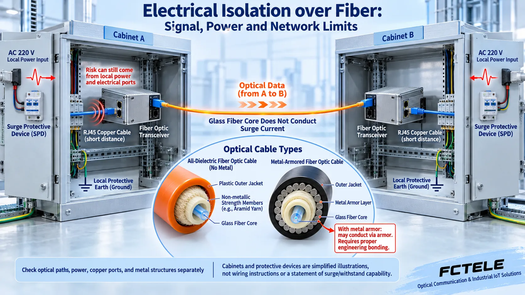
The potentials of two grounding points are not always the same. Cross-site metal communication lines and their shielding layers, as well as other metal connections, may bring unwanted current or common-mode disturbance. All-dielectric fiber cable uses non-metallic components and can avoid introducing a cross-site metal path through this communication medium. However, if shared power supplies, copper management lines, or other connections still exist on site, the conductive relationships at the system level must still be confirmed item by item.
“Having fiber” does not mean “the entire cable has no metal.” Some fiber cables have metal armor, metal strength members, or are used in combination with power conductors. Check the fiber cable structure and installation documents, and handle metal components according to engineering requirements. Do not ignore them just because the fiber core is glass. Equipment protective grounding must not be removed without authorization in pursuit of isolation.
The optical path does not conduct current, but that does not mean surge protection is completed for the power port and Ethernet electrical port. When lightning protection is needed, ask clearly which port, what test conditions and level, and how the associated grounding and protective devices are installed. IEC 61000-4-5 discusses test methods and conditions for surge immunity. The words “with optical port,” “industrial grade,” or promotional “lightning protection” cannot replace the test basis for the selected complete device and ports.
When selecting equipment, first use specific capabilities to solve specific faults
First list interface rate, single-mode or multimode, dual-fiber or single-fiber, matching optical modules at both ends, power supply, and environmental conditions, then look at maintenance capabilities. A dual-fiber link usually connects local TX to remote RX. Bidirectional single-fiber must use a matching transmit and receive wavelength combination. Transmission distance is one selection condition. In practice, also check transmit and receive optical power, line loss, and receive upper limit, not just the nominal kilometers in the model.
The Feichang Technology website’s “Managed Industrial 1-Fiber 1-Ethernet 100M Fiber Optic Transceiver” details describe capabilities such as viewing local and remote interface status, power loss detection, redundant dual power inputs, and power protection. Remote status and power loss distinction help determine “is the optical path broken or is the remote end out of power?” Redundant power supply helps handle a single power path failure. These are targeted maintenance functions. They do not automatically turn a service network into a securely isolated network.
The model column on that detail page does not give a complete model that can be confirmed from it. Therefore, when ordering, confirm the specific configuration and hardware version. The power supply range and surge capability should be confirmed by the corresponding documents and test records. Do not extend the general wording on the page to all products. If two power supplies still depend on the same upstream power source, or if the fiber cable is routed along the same path, “dual power supplies” alone cannot be used to conclude that there is no common failure point.
For a cross-workshop scenario, how should acceptance be done usefully?
Suppose a camera is in Workshop A and the monitoring host is in Equipment Room B. The original long copper cable connection is unstable when a large motor starts and stops. Matching media converters can be installed near both ends, the cross-workshop section can be replaced with fiber cable suitable for the installation environment, and short network cables can be kept at both ends with local power handled. This example explains a retrofit approach. It cannot be used to guarantee that a particular site is definitely caused by electromagnetic interference, and it is not a Feichang Technology customer case or test result.
For acceptance, first perform a short-distance paired test during a maintenance window to confirm the interface mode and matching at both ends, then connect to the formal optical path. Record optical power, link status, port error statistics, device uptime, and logs. Carry out continuous transmission according to the actual service and observe whether packet loss, reconnection, or restart occurs when the motor starts and stops normally. The test load should be agreed in advance. A single successful Ping cannot be used to declare stability.
When a fault occurs, first check whether the device restarted, then check whether the optical port has lost light and whether the electrical port is down. Replace items one by one with known-good power supplies, short network cables, and optical modules, and keep records before and after replacement. Do not inject surges into powered equipment yourself, create high-voltage tests, or remove protective grounding to verify “isolation.” These items require corresponding test conditions and personnel. On-site acceptance checks installation and service performance. It cannot replace withstand voltage and immunity certification.
Common misunderstanding: passive optical components are not a security boundary
A splitter is used to distribute light. A wavelength division multiplexer is used to combine or separate different wavelengths. “Passive” only describes how it works. It cannot be used to infer message encryption, identity authentication, auditing, or attack resistance. In optics, an “optical isolator” is usually used to suppress reflected light feeding back into a laser. It is not the same kind of device as isolation between a production network and an office network.
An ordinary fiber optic transceiver lets data cross the optical path during normal operation. That is exactly its purpose. It does not become a firewall or security gateway just because the medium changes. In engineering, accept optical path transmission, power and port protection, and service access boundaries separately, and keep evidence separately. In this way, you can use the interference immunity advantages of fiber without misreading “fiber does not conduct electricity” as meaning the entire network is absolutely secure.
Reference note: The two main principle diagrams and the separate list thumbnail are general mechanism illustrations. They have been checked for technical content and are used to explain general mechanisms. They are not actual product photos, wiring manuals, or measured records. Product capabilities are confirmed according to the selected model, configuration, and version.
Verification references: Feichang Technology industrial managed media converter category
Feichang Technology managed industrial 1-fiber 1-Ethernet 100M fiber optic transceiver (detail 574)
TI: Fiber in Industrial Applications
Corning: All-dielectric fiber cable construction description
IEC 61000-4-5: Surge immunity test
Newport: Faraday Optical Isolators
Feichang Technology 812: Difference between physical isolation and logical isolation
Common on-site questions
If cross-workshop communication is changed to fiber, is the entire equipment set completely electrically isolated?
It can only be said that a suitable non-metallic fiber section does not use a copper conductor to carry signal current. The system may still form conductive relationships through shared power, copper management lines, metal components, or other wiring. Draw the paths clearly item by item and handle them according to engineering design. Do not remove protective grounding without authorization for isolation, and do not derive complete-device withstand voltage rating from one fiber cable.
Fiber does not conduct electricity, so why can the media converter still be damaged during thunderstorms?
The power port, Ethernet electrical port, and other metal paths on site may still experience disturbance, and the fiber cable may also have metal armor. Surge capability must correspond to the specific port, waveform, test conditions, and installation requirements. The dielectric advantage of fiber is not a direct lightning strike guarantee. On site, do not apply high voltage or surges yourself to verify protection.
If a fiber optic transceiver is used to connect a production network and an office network, is secure isolation achieved?
No. An ordinary fiber optic transceiver normally lets data cross the optical path. Electrical non-conduction does not prevent message forwarding. Access permissions, network segmentation, authentication, and auditing must be designed and accepted separately. An optical isolator is used to suppress optical problems such as reflection. It is not another name for a firewall or network security gateway.
Continue reading: How does a serial server connect to the network safely: access control, encrypted channels, and industrial site protection ; How does a digital input/output fiber optic transceiver isolate signals: fiber, electrical interfaces, and interference immunity boundaries ;
Translated from the Chinese technical article. Source first published: 2024-12-26. Source last revised: 2026-10-15T19:44:23.840277+08:00. Read the Chinese source
