


Synchronization in SDI does not have only one meaning. The receiver needs to know when to judge each bit, and also needs to identify the position of video lines and active picture; the studio may also require multiple cameras to output under the same reference rhythm. The three are related, but they are not the same thing. An SDI fiber optic extender can recover the bit clock of one link, which does not equal automatically making multiple video sources achieve frame synchronization.
1. Why high-speed pulses need a clock
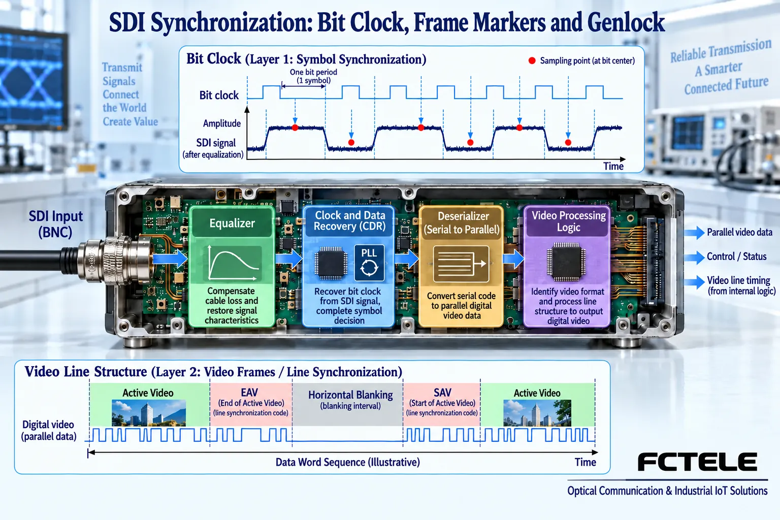
SDI sends information in a serial manner, and the receiving circuit must read zeros and ones at the appropriate moment. After transmission, the edges will be affected by attenuation, noise, and jitter, and it cannot rely only on a local oscillator with approximately the same frequency for long-term reading. Clock and data recovery is usually abbreviated as CDR; it uses changes in the input signal to track the bit rhythm and arranges data decisions within the allowed range.
The clock here corresponds to serial bits, and is not another name for the display refresh rate. Each video frame contains a large number of samples, timing, and auxiliary information, and the transmission rate is also affected by data mapping. Seeing 2.97Gb/s does not directly infer that the camera must output a certain resolution or frame rate. The same physical rate may carry different formats, and the same format may also use different mappings, so it is necessary to continue checking the specific standard and device capabilities.
2. How lines and active picture are identified
The deserialized digital word sequence not only contains picture samples, but also contains information used to locate timing. The receiving video circuit identifies line boundaries, the active video area, and the blanking area according to the corresponding SDI system, and only then knows where the subsequent data is located in the picture. Timing reference information is often described by the term TRS, which is different from simply detecting pulse edges; being able to find the bit rhythm does not mean the receiver has understood all video content.
It can be compared to first recognizing each character, then recognizing paragraph boundaries, but the actual circuit is not reading text. Incorrect bits or unsupported data mapping may affect subsequent structure identification. Auxiliary data may also carry information such as embedded audio, which needs to be parsed by the corresponding circuit. If the fiber optic extender only transparently extends, it does not necessarily interpret or regenerate every video field, and it cannot be given an intelligent frame repair function that is not supported by the documentation.
3. Why 3G compatibility still requires checking the mapping
The rate tier of 3G-SDI cannot replace a complete compatibility check. Level A and Level B involve different organization methods; some devices can handle one of them or perform conversion, and some devices cannot. The receiver being able to recover the serial clock only proves that one stage may work; whether the monitor understands that mapping, color sampling, and scanning method is another requirement later. During procurement, the source output mode should be provided as-is to the supplier for confirmation.
When the system upgrades from HD to 3G or 12G, the source, coaxial cable, input processing, optical module, output driver, and receiving terminal should be checked at the same time. Replacing only the camera or optical module cannot guarantee that the entire link will be upgraded accordingly. The Feichang Technology website lists one-channel 3G and one-channel 12G products separately, and the rate tier should be checked according to the specific order configuration; the fact that a product has an automatic identification function also cannot prove that it accepts all possible video mappings.
4. Why multi-camera synchronization needs another reference
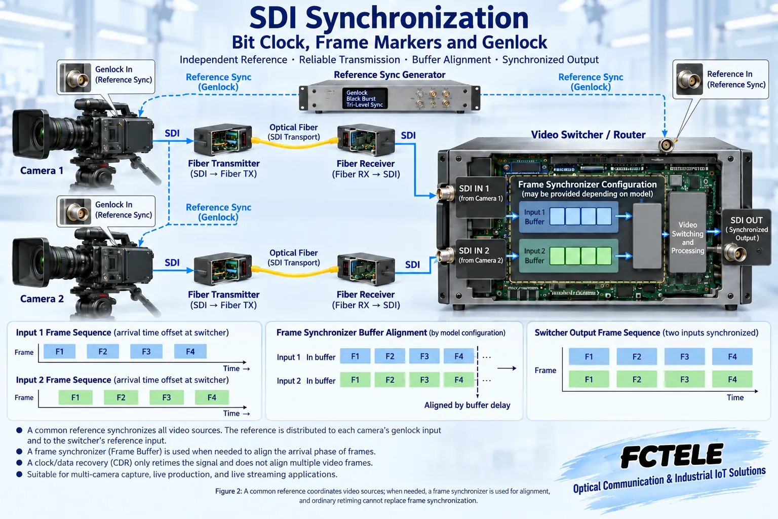
When a studio switches multiple pictures, it hopes that the lines and frames of different video sources are in a manageable relative position. Cameras with the corresponding interface may use an external reference for phase locking, usually called genlock. The goal of a reference synchronization system is to coordinate multiple sources, while CDR recovers the serial rhythm transmitted by one path at the receiving end. Replacing all fiber optic extenders with models that have retiming will not automatically establish a common frame reference for all cameras.
When there is no common reference or there are path delay differences, the switcher may use a frame synchronizer to align the input to the output rhythm. Frame synchronization involves buffering and timing adjustment of the picture, which may introduce delay, and is different from retiming that only handles high-speed serial edges. Whether the actual switcher has a built-in frame synchronizer, which formats it supports, and how much delay it adds must all be checked in the model documentation, and cannot be directly inferred from the words “digital video” or “synchronous transmission”.
5. Find the corresponding layer along the symptoms
If the receiver repeatedly loses lock, first check the input signal quality, rate, power supply, and optical receiving conditions, rather than first adjusting the multi-camera reference. If single-channel monitoring is normal, but there is jumping during switching or the switcher indicates unsynchronized, then check the reference source, camera synchronization settings, and the switcher’s input processing. If the clock is locked but there is always no picture, continue checking the mapping, scanning method, and terminal support, rather than treating the lock indicator as proof that the format is correct.
For example, two cameras both output 1080p50 and are sent to the switcher after passing through two optical paths. Both paths can display, indicating that basic transmission may be established, but fiber length, device processing, and source timing may still cause relative differences. Engineers should first confirm the switcher requirements, then decide whether to use a common reference or input frame synchronization; the task of the fiber optic extender is still to reliably transmit each SDI path, not to replace the studio synchronization architecture.
6. What to record to make acceptance repeatable
Record the source’s complete video mode, interface rate, mapping, external reference settings, and the identification result displayed by the terminal. When multi-camera alignment is needed, also record the distribution method of the reference signal and the switcher processing mode. Writing only “HD signal synchronization normal” cannot distinguish bit lock, line structure identification, picture display, and multi-camera frame alignment, nor can it allow another engineer to repeat the same test.
During continuous operation, observe whether error counts, loss of lock, image, and audio are stable; when a professional analyzer is available, check according to the indicators supported by the device. The pulses and video line structures in the figures are teaching illustrations, not measured results of a particular product. A truly reliable synchronization conclusion should correspond to a clear layer, clear equipment, and clear test conditions, and a schematic diagram cannot be used as evidence that all models have synchronization performance.
When audio-video synchronization is involved, it should also be checked whether the audio is in the required relative timing with the corresponding picture. The delays of the transmission link, audio processing, and frame buffer are not necessarily the same, and it cannot be assumed that the final sound-picture relationship is correct merely because all video inputs are locked. Only by clearly writing down the synchronization objects required by the system can appropriate measurement and adjustment methods be selected.
Sources: SMPTE standard index ; AJA dual-link and 3G mapping explanation ; AJA frame synchronization product and mechanism materials ; Feichang Technology one-channel 3G SDI fiber optic extender ; Feichang Technology one-channel 12G SDI fiber optic extender . The principle illustrations are general mechanism illustrations, not product photos, measured waveforms, or certification documents.
Related topics: How does an SDI fiber optic extender work: coaxial reception, clock processing, and optical-electrical conversion ; SDI fiber optic extender signal processing: what equalization, clock recovery, and retiming each solve ; How to test and accept an SDI fiber optic extender: format, bit errors, optical power, and continuous operation ; How to evaluate SDI fiber optic extender power consumption and temperature rise: power loss, heat dissipation, and operation arrangement ; SDI fiber optic extender installation and troubleshooting: short-cable baseline, optical path activation, and segmented localization ; How to choose between SDI monitoring and IP monitoring: transmission, recording, latency, and security boundaries ; How to check no picture or no sound when converting SDI to HDMI: power supply, lock, and display compatibility
Common on-site questions
If the SDI fiber optic extender recovers the clock, will multiple cameras automatically synchronize frames?
No. CDR recovers the bit rhythm of one serial data path, while studio multi-camera synchronization needs to coordinate the line and frame timing of different sources. Whether to use a common reference, genlock, or input frame synchronizer should be determined by system requirements and specific device support. Having a retiming function cannot replace a complete synchronization architecture, nor can it directly guarantee audio-video synchronization.
Both ends are marked 3G-SDI, so why is it still possible to lock but not have the correct picture?
The physical rate tier cannot replace complete format matching. It is also necessary to check the scanning method, resolution, frame rate, Level A or Level B mapping, and terminal support. Lock is only one layer of status; the source’s complete output mode and the receiving end’s identification result should be saved, not just a rate label.
If a single-channel picture is normal but jumps during switching, should the optical module be replaced first?
Do not jump to a conclusion directly. First confirm single-channel errors and loss of lock, then check the camera reference, switcher input synchronization, and relative delay. Normal link transmission and multi-channel timing alignment are two issues. Fix the format and configuration each time, change only one condition, and judge using device-supported statistics and actual switching performance.
Continue reading: How does a fiber optic extender transmit signals? Principles of electrical-optical conversion and receiving recovery ; How to look at USB fiber optic extender speed and latency: shared bandwidth, transmission type, and measured acceptance ;
Translated from the Chinese technical article. Source first published: 2024-12-19. Source last revised: 2026-10-15T19:44:23.840277+08:00. Read the Chinese source
