


First distinguish where to send and when to send
After an Ethernet switch receives data, it needs to decide which port to send it out from, and also when to start sending it. Source MAC address learning and destination address table lookup mainly answer where to go; cut-through, store-and-forward, and fragment-free forwarding mainly describe the timing relationship between receiving and sending. They are not three industrial communication protocols, nor do they mean a product necessarily provides three switchable buttons. Industrial attributes and forwarding mode should be checked separately.
For example, a camera sends a frame of data into the switch, and the uplink port then hands it to the recording server. Even if the address table is correct, when the uplink is busy it may still need to wait. This article uses one receiving direction to explain the mechanism, and does not represent a real customer case or the internal wiring of a particular chip. When selecting a model, look at the complete function together with the actual path, and do not compare only the fast or stable in the name.
Why the FCS at the end of the frame affects check timing
Ethernet organizes data into frames. The frame header contains link addresses, and the frame trailer has a frame check sequence, FCS. The receiving end calculates a result according to cyclic redundancy check, CRC, rules and compares it with the FCS, which can detect corresponding transmission errors. It is not responsible for repairing data, and it is not encryption or identity authentication; passing the check also does not mean the application instruction is correct, safe, or timely.
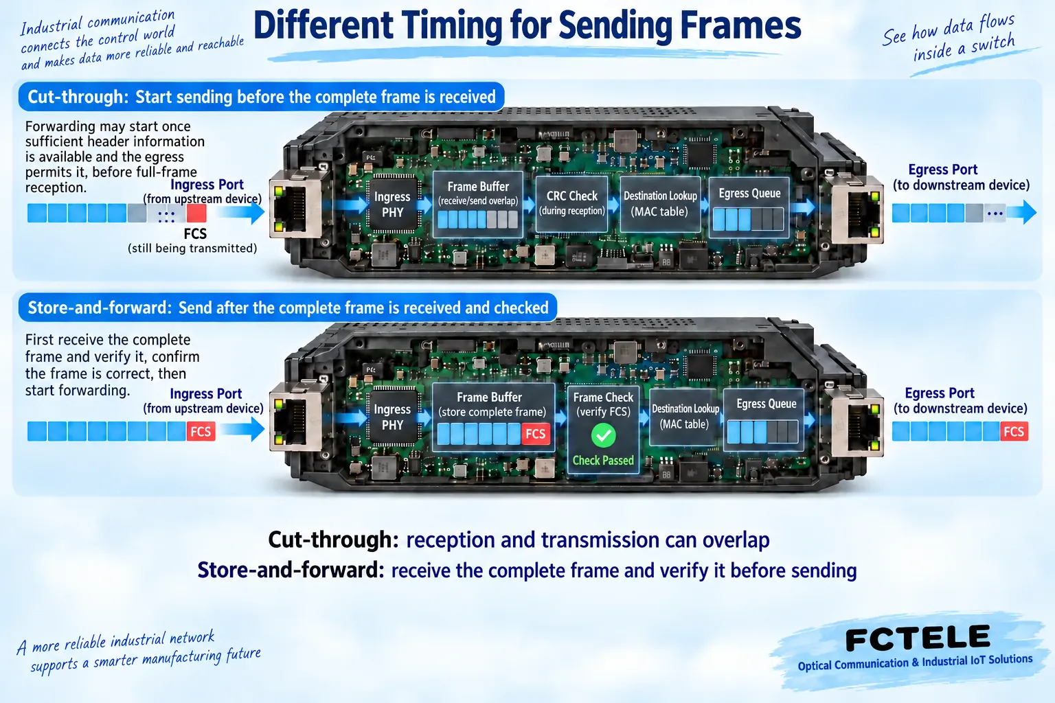
For a long frame that has not yet been fully received, the trailing FCS has not arrived, and the check conclusion for the complete frame has not yet been formed. Therefore, sending first and completing the check first involve different processing timings. The colored frame blocks in the figure only represent data in receiving order, and are not objects that can be directly seen on the interface; complete frame checking also needs to be combined with the device’s length check and other receiving rules.
Cut-through overlaps receiving and sending
Cut-through forwarding allows sending from the egress to begin before the entire frame has been received. The device must already have obtained enough information to make a forwarding decision, and the egress and internal processing conditions must allow it; you cannot write all models as starting to send after receiving only a fixed number of bytes. The fields that need to be parsed, function configuration, and implementation all affect the starting point.
The receiving tail and the sending front part can overlap in time, reducing part of the time spent waiting for complete reception. But if an abnormality is found at the tail, the earlier content may already have been sent downstream. Some implementations mark the bad frame as a check exception so that later receivers can identify it, so you cannot therefore say that errors have all been intercepted before sending at this level. Low latency does not equal zero latency or no error handling.
Store-and-forward first forms a complete reception result
Store-and-forward first receives the complete frame, performs frame checking and length checks according to the implementation, and then hands the forwardable frame to egress processing. Bad frames that can be identified before sending can be discarded at this level. The diagram separates the steps for easier understanding; actual table lookup, reception, and checking may be parallel, and the teaching diagram should not be treated as a step-by-step serial process that vendor hardware must follow.
Complete reception brings waiting, but this is only part of the device processing time. If the egress already has traffic, a correct frame still has to wait for scheduling; if there is no congestion, you also cannot infer from this that system response is determined by only one mode. Port rate, message length, enabled functions, terminal processing, and other devices along the path may all affect the final service experience.
Fragment-free mode does not check all long frames
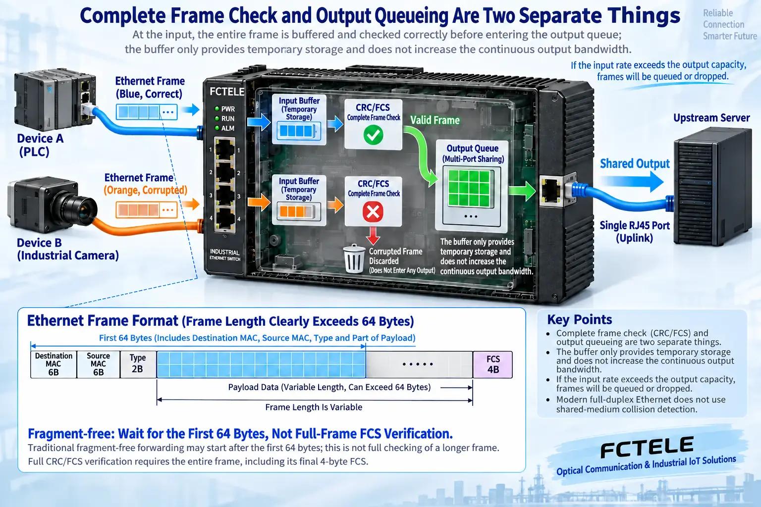
Traditional fragment-free mode usually waits until the first sixty-four bytes of the frame have been received before starting forwarding. One purpose is to avoid continuing to send short collision fragments from shared half-duplex Ethernet. It is a variant of the cut-through idea, and because the name says fragment-free it cannot be interpreted as error-free. For frames longer than this length, the tail may still not have arrived, and complete FCS checking cannot be replaced by the front part.
Today’s common full-duplex switched links do not rely on the shared-medium collision mechanism to work, so the historical compromise method should not be treated as a necessary function for all industrial sites. Whether a chip implements it, whether a product exposes configuration, and under what conditions a specific port uses it should all be based on valid documentation. There is no universal ranking that ranks all models by advancedness based only on the three names.
Buffering and egress capacity are another limit
Frames from different ingress ports converge to one egress port, and the egress can only send corresponding data at its actual rate at one time. Buffering can temporarily store burst traffic, but it cannot provide throughput exceeding egress capability for a long time. When continuous input is excessive, queues will increase, which may bring waiting and discarding. Treating the minimum forwarding waiting time as service latency at full load will miss this main factor.
When rates differ, buffering and scheduling conditions also need to be checked. A slow ingress to a fast egress may need to wait for enough data, while a fast ingress to a slow egress needs to absorb the difference; whether a certain cut-through path can actually be maintained depends on the device implementation. You cannot write all different-rate situations as the same fixed action, and you certainly cannot use a large buffer to prove that continuous overload will never drop packets.
During troubleshooting, record check exceptions received on the port and egress queue discards separately: the former suggests a possible problem with the receiving link or upstream data, while the latter may be related to congestion or policy. They are not the same fault count. When a bad frame is found on a cut-through path, also check the error records upstream and downstream along the data direction; seeing an abnormality only on the last device does not directly determine that the damage must have originated from it.
How Feichang Technology specific products correspond to the mechanisms
The Feichang Technology mini industrial rail-mounted managed 2-fiber 4-copper product page with RSTP ring network explicitly lists store-and-forward mode, and provides function descriptions such as optical and electrical access, VLAN, IGMP snooping, and queues. It can serve as a reference object for cabinet site access and fiber uplink: store-and-forward answers the reception check question, VLAN and multicast functions answer the service scope question, and RSTP answers the topology recovery question; they cannot replace each other.
That page does not have enough explanation to prove that all three forwarding modes can be freely selected, so this article does not promise cut-through configuration, minimum latency, or compatibility with all control protocols on behalf of the product. The ordering interface, firmware, and applicable specification should be confirmed; optical ports and port management functions still need to be configured according to version. The general mechanism diagram is not a physical object of this product, and the number of queues or processing modules in the diagram are not used as model parameters.
Complete acceptance with comparable records
In an approved isolated test environment, first fix the device version, port rate, frame length, path, and enabled functions, then observe throughput, latency changes, errors, and discards under the target load. When comparing modes, only if the device truly supports switching can you test while keeping other conditions consistent. Different test tools may use different latency start and end points, and the report must state the definition.
RFC2544 provides a methodological reference for benchmark testing of network interconnection devices, but it is not an instruction for site personnel to directly flood the production network, nor is it a unified certificate of real-time performance for industrial control. Acceptance must also return to the business task: whether data is complete, whether response meets requirements, and whether abnormalities can be located. Saving the configuration and test conditions is what allows send timing, check results, and queuing effects to be explained clearly.
You can separately arrange a contention-free single-ingress single-egress observation and a multi-ingress converging shared-egress observation. The former helps understand basic processing, and the latter helps reveal queuing effects. Record again after changing to different frame lengths, rather than writing the round-trip time of one no-load Ping as the switch’s per-frame forwarding time. Ordinary computers and application software may also introduce changes, so tool capabilities and measurement scope should be stated, and abnormal samples should not be deleted just to obtain nice-looking values.
Documentation note: The principle diagrams have been checked against technical content and are used to explain general mechanisms; they are not physical product photos or measured records. Specific interfaces, modes, and capabilities are subject to the selected model, version, and on-site verification.
Reference materials: Cisco Networking Academy: Switch forwarding modes
Cisco: Cut-through switching and CRC error location
RFC2544: Benchmarking methodology for network interconnect devices
Feichang Technology mini managed 2-fiber 4-copper product details with RSTP ring network
Feichang Technology managed rail-mounted industrial switch category
Related technical topics: Industrial switches and commercial switches: environmental evidence is more important than the enclosureHow to choose industrial switches for harsh environments: temperature, condensation, protection, and installationHow to choose a managed industrial switch: ports, uplink, and on-site verificationHow to choose a fiber industrial switch: SFP matching, optical power, and acceptance
Translated from the Chinese technical article. Source first published: 2020-12-01. Source last revised: 2026-10-13T11:20:43+08:00. Read the Chinese source
