


Start with the conclusion
Start with the conclusion: a closed optical path also needs corresponding control mechanisms
A serial fiber ring network connects distributed nodes through optical paths, and devices that support the relevant functions adjust the communication path when a fault occurs. It is suitable for serial acquisition tasks that need path redundancy, but physically forming a circle does not mean that any point-to-point fiber modem can self-heal, nor does it mean that multiple masters can be placed at the same time without rules.
Before networking, confirm the business roles, interface modes, channel correspondence, optical pairing, and device redundancy mechanisms. This article uses four nodes N0, N1, N2, and N3 to explain paths; the number and station addresses are teaching examples. The request direction and reply direction are separated, and the diagram is not treated as the internal algorithm or switching performance commitment of a specific model.
First determine at the business layer: who queries, and which slave answers
In typical two-wire RS485 polling, the master sends a request, the specified slave responds, and other slaves remain silent according to the protocol. The ring network extends the path; it does not assign addresses to instruments or eliminate message conflicts. If two drivers transmit on the same copper segment at the same time, collisions can still occur; application-layer arbitration cannot be automatically supplied by a single fiber cable.
When a project uses one master, list the master, slaves, station addresses, and channels clearly. The fact that a device configuration can select a role does not mean that any multi-master system is supported. Multiple serial channels also need to be checked to see whether they are independent, shared, or crossed; having more terminals does not mean the master software can freely access them simultaneously.
How nodes pass data between copper and fiber
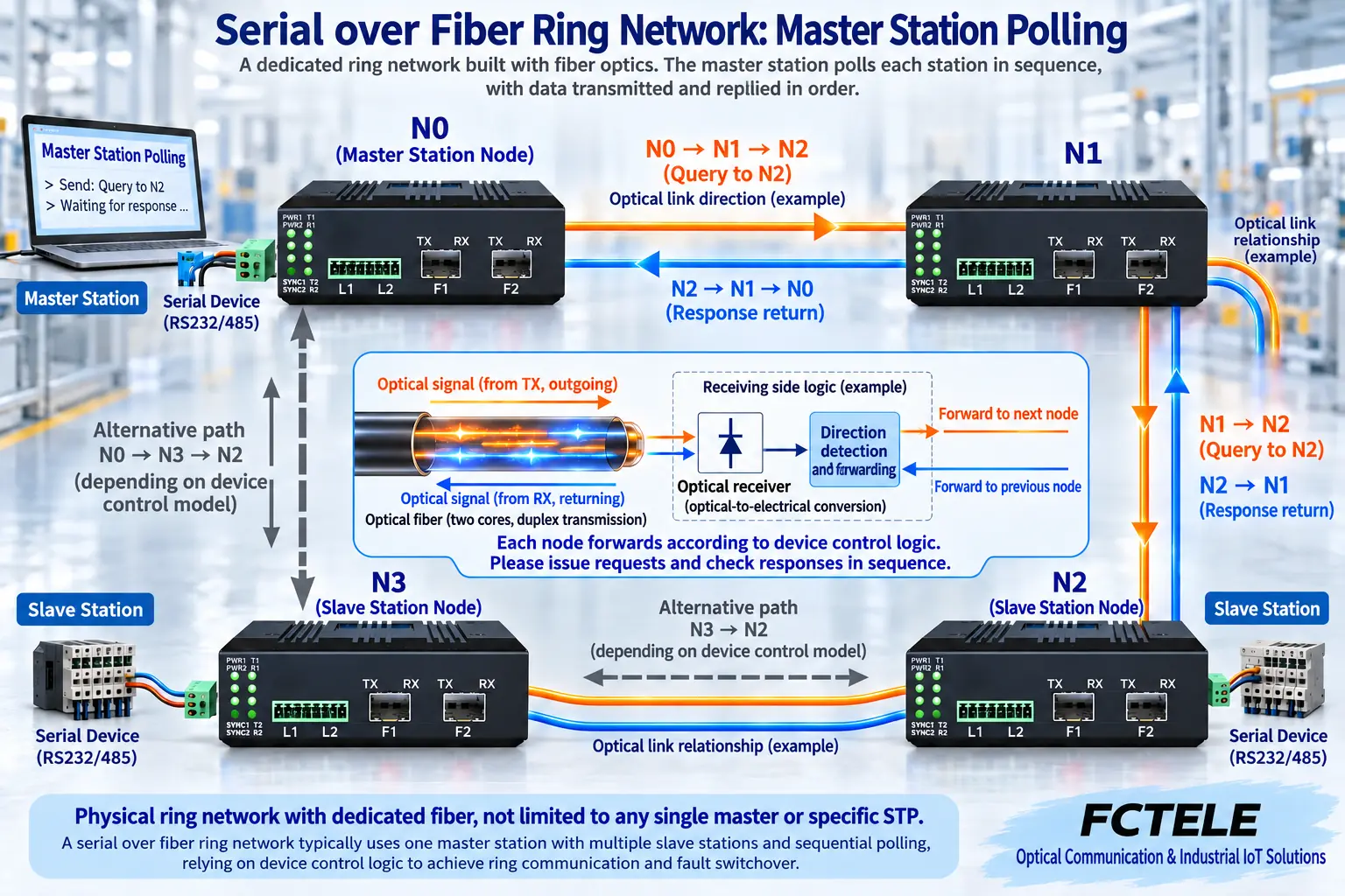
The local serial receiver obtains electrical logic information, internal circuits organize channels and control optical transmission according to the design; after receiving light, the adjacent node restores the data and, according to the device mechanism, continues to pass it on or outputs it to the local serial port. The optical path carries supported serial information; it does not move all voltage noise on the copper line to the next station.
Nodes also need to handle which optical direction a message enters from, how to forward it, and how to prevent duplicate or meaningless return. Two optical ports only prove that there are two interfaces; they do not prove that all devices use the same redundancy control. Serial fiber modems, Ethernet switches, and serial servers handle different services, and even if the connectors are the same, they cannot be directly mixed into one ring.
In the teaching diagram, when querying N2, the example path is N0 to N1 and then to N2; the reply goes from N2 through N1 back to N0. The other physical path through N3 is the backup. Whether it forwards normally, how faults are judged, and how the direction is selected must all be checked against the corresponding manual; do not arbitrarily mark all models as always blocking a certain port.
Why backup paths must be controlled
A closed loop provides multiple possible physical paths, and at the same time requires the device to have corresponding forwarding and fault management. Without the corresponding design, simply closing the line may cause duplication, conflicts, or no communication. Ethernet mechanisms such as STP, RSTP, or ERPS also cannot be transplanted to serial fiber transceivers without basis.
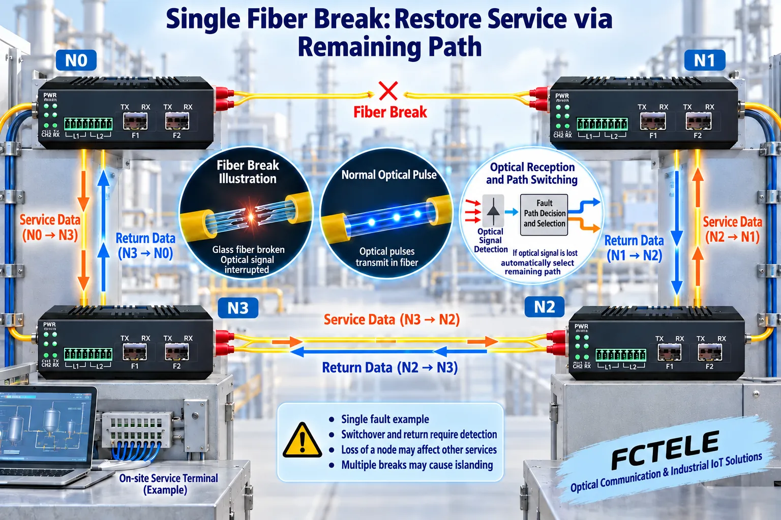
After one optical path is interrupted, if the remaining path still connects the master and the target node, only devices that support this condition may be able to adjust forwarding. Detection, switching, and upper-layer retries all take time, and during the process there may be message loss or timeouts. Whether the acquisition cycle is met should be measured with real data, load, and node scale, and should not be written as zero interruption.
After the original optical path is restored, the switchback or path stabilization process also needs to be verified. Whether the master receives duplicate responses, old data, or abnormal frames cannot be proven only by one indicator light returning to normal. Both the request and reply directions must be continuously recorded, especially for time-sensitive and execution-type services.
Discuss fiber breaks, power loss, and multiple faults separately
When a single fiber cable segment is broken, the diagram shows that N0 can still reach N1 through N3 and N2, and the remaining path may serve nodes on both sides of the fault. But power loss at the node itself is another matter: its local instrument service is usually affected, and whether other services can bypass it depends on the remaining optical path and device implementation. Self-healing does not equal automatically repairing faulty hardware.
Two fiber breaks may separate some nodes into islands with no master path, and software cannot create a physical connection out of nothing. Optical module failure, power failure, device restart, and copper line break also have different scopes of impact. Writing clearly at the design stage the single faults that are allowed to be covered and the fault conditions that are not covered is more useful than writing only “redundancy.”
The middle section of the fiber has no metallic data conduction, but endpoint power, copper lines, and enclosures still need independent protection. Redundant dual power supplies also do not mean that connecting two wires to the same power supply is enough; if the physical routes of the optical paths both pass through one vulnerable location, they will also be affected by a common fault. The independence of paths and power supply must be implemented on the engineering drawing.
Confirm interfaces and two optical lines with FC2P-D/Q/R
Feichang Technology FC2P-D/Q/R product documentation lists 1–2 serial ports, DIP setting of interface type, two optical line fault switching, and corresponding topology options. This provides a specific object for checking a serial ring network; the actual number of channels, interface modes, master-slave relationship, node compatibility, and optical components must be confirmed according to the delivered version, and optional items should not be treated as all being present on every machine at the same time.
The serial rate range and port forms in that documentation can be used for order checking, but automatic identification and direction control still require real terminal acceptance. For each optical segment, separately confirm single-mode or multimode, single-fiber or dual-fiber, transmit-receive pairing, end face, and power budget. On the serial side, check parameters, station addresses, and local terminal bias; do not skip copper segment conditions just because an optical ring is formed.
Make fault recovery into a record with start and end times
First, on the bench according to the manual, let the master stably read each slave, then connect the formal optical path. Save the normal channel table, port status, query frequency, requests and replies, and error counts. In an approved maintenance window, simulate one fiber break, record the last successful moment, the moment success resumes, which nodes are affected, and the abnormalities and duplicates after recovery.
Separately arrange tests for master restart, single-node power loss, and optical path recovery, and define in advance the acceptable scope of impact and rollback steps. Execution-type commands need to check confirmation, retry, and deduplication mechanisms to prevent repeated actions during recovery. Do not arbitrarily disconnect lines for testing directly on a running production system.
Deliver the master-slave and address table, fiber paths, device configuration, normal baseline, fault results, and recovery procedure. The final conclusion should be “under these configurations and these fault conditions, the service performance meets the agreement,” rather than summarizing any fault as the ring network automatically recovering.
Documentation note: The illustrations use original product photos from the Feichang Technology official website as appearance references; the scenes and physical mechanism enlarged diagrams are checked, and are not teardowns, measured waveforms, or real project sites of the corresponding model. The line relationships in the diagrams are used to explain mechanisms; actual wiring and power supply are subject to the delivered model and manual.
Verification materials: TI: RS-485 electrical interface and bus design
FOA: Optical link budget and loss
Feichang Technology FC2P-D/Q/R serial fiber ring network product
Feichang Technology single-channel serial fiber modem category
Translated from the Chinese technical article. Source first published: 2021-04-14. Source last revised: 2026-10-13. Read the Chinese source
