


First separate the sound signal from the digital samples
The sample rate and bit depth of an audio optical transceiver answer, respectively, how often the input voltage is read and how many bits represent each reading. They help in understanding the device, but they cannot by themselves prove the sound quality of the entire link. A digital optical transceiver used to extend analog line audio first turns the audio voltage into samples, then transmits them to the far end for reconstruction; a native digital audio interface already receives a digital bitstream and may not perform another analog-to-digital conversion.
The line output of a player or mixing console passes through input circuitry, filtering and an analog-to-digital converter ADC to form digital samples. The device organizes the samples of each channel into a transmission bitstream, sends them through the optical transmitter and fiber to the receiving end, and then a digital-to-analog converter DAC and reconstruction filtering restore the analog voltage. Each stage has its own limits; even if optical transmission is complete, it does not mean the input, conversion and output are all error-free.
Sample rate is time density, and cannot be written as sampling precision
Sample rate is expressed as how many samples per second, for example 48 kHz means forty-eight thousand times per second. It determines the spacing of samples on the time axis. For a band-limited signal, the sampling frequency must be higher than twice the highest frequency retained; in engineering, space must also be left for the filter transition band, and exactly twice must not be treated as a guarantee that actual equipment can unconditionally recover the boundary frequency.
Anti-aliasing filtering is used to limit out-of-band content before sampling. Without suitable filtering, higher frequencies may fold into erroneous components within the band after sampling, and this cannot be corrected later simply by increasing playback volume. 44.1 kHz, 48 kHz and 96 kHz are different sampling configurations and should not be directly ranked as levels of good sound; a project must look at the actual bandwidth, processing chain and the configurations supported by all devices.
Bit depth is the amplitude scale, and transmission bitrate is calculated separately
Bit depth is expressed in bits, for example 16 bit or 24 bit, and describes the number of binary digits used for each sample. Ideally, the more bits, the finer the amplitude scale that can be represented. Quantization is the process of assigning a continuous voltage to these finite levels, which creates quantization error; it does not mean the input is truly noise-free, and it will not automatically repair incorrectly wired lines or sound that has already been distorted by an amplifier.
Transmission bitrate is expressed in bit/s. If we assume two mono channels both use 48 kHz, 24 bit and are uncompressed, the net sample data rate alone is 48000 times 24 times 2, giving 2.304 Mbps; this does not include frame headers, synchronization, line coding or other services. This number is a teaching calculation, not the optical port rate of any particular optical transceiver, and it cannot be used to infer that any transmitter and receiver can interoperate.
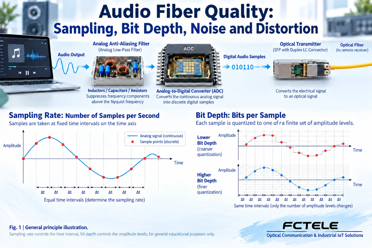
A 24-bit label cannot replace a complete-device noise measurement
For an ideal quantizer under specified conditions such as a full-scale sine wave, the quantization signal-to-noise ratio increases by about 6 dB per bit as the number of bits grows. This theoretical relationship cannot be rewritten to mean that a 24-bit complete device must have 144 dB of dynamic range. Real equipment also has noise and distortion from the analog front end, power supply, clock, conversion circuitry and output section, so the complete-device test conditions and measurement results should be checked.
Signal-to-noise ratio describes the size of the signal relative to noise, while dynamic range and total harmonic distortion have their own definitions and measurement methods. Whether weighting is specified, the input level, test frequency, output load and measurement bandwidth all affect comparison. Confusing the three metrics, or substituting a chip’s theoretical limit for the complete-device specification, can make a purchase look numerically high but fail acceptance.
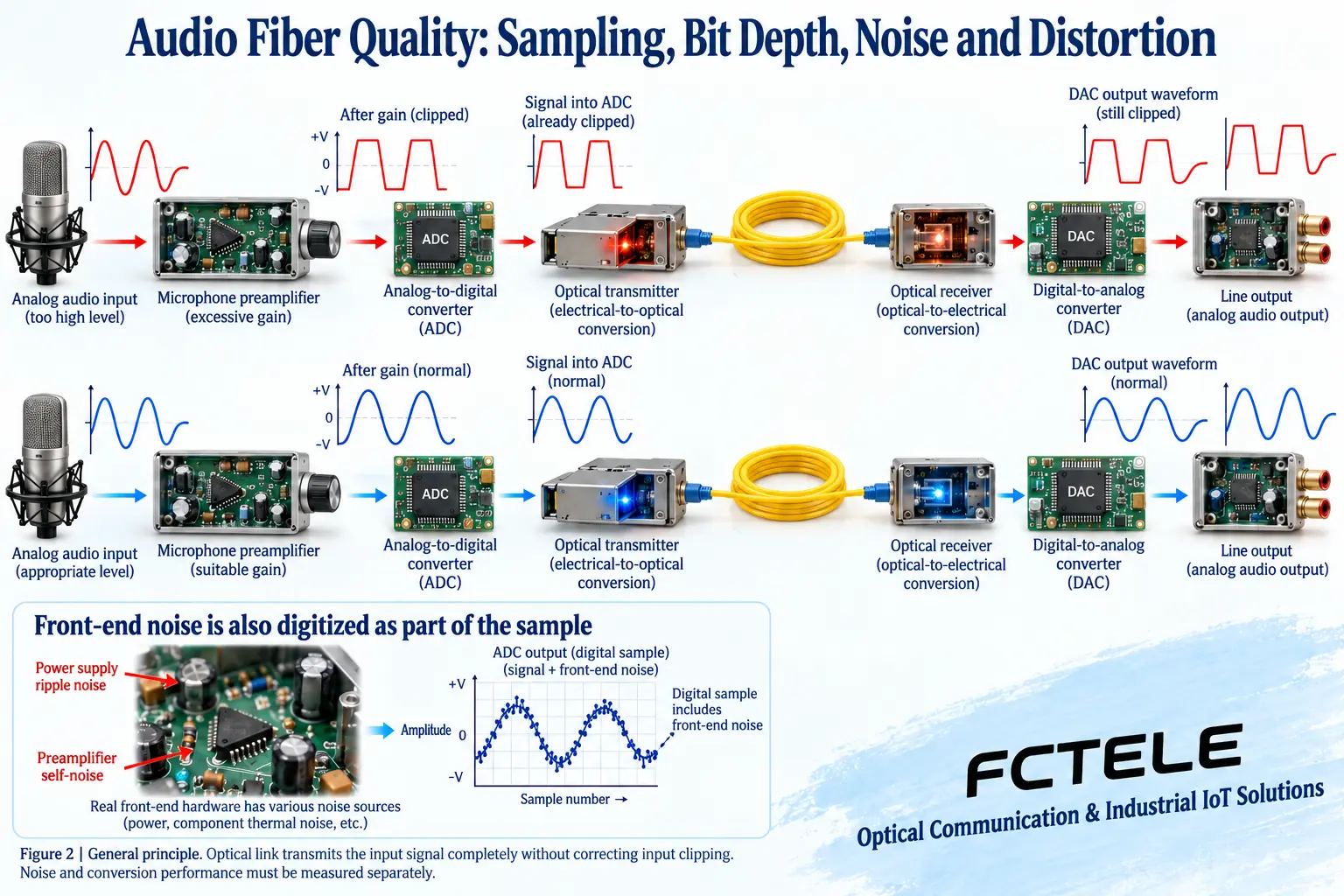
Input clipping and the noise floor enter the digital samples
When the input exceeds the allowed range, the peaks of the waveform are flattened, which is called clipping. The ADC records the clipped voltage, and even if the receiving end accurately restores these samples, it cannot reconstruct the original peak shape. Conversely, if the input is too small and the later gain is very high, the front-end noise will also be amplified. Allocating gain reasonably solves these on-site problems better than blindly choosing higher sampling parameters.
Microphones, line outputs and amplifier speaker outputs are not the same level. An ordinary line input cannot directly withstand an amplifier power output; whether a microphone can be plugged in directly depends on the preamp gain and power supply. Digital optical transmission itself does not automatically provide noise reduction, compression, echo cancellation or volume equalization; these processing functions must be checked for the specific product and cannot be assumed from the word “digital”.
Before raising parameters, check both ends and the system configuration
A higher sample rate increases the number of samples per unit time, a higher bit depth increases the amount of data per sample, and more channels also increase the total demand. Comparison is meaningful only when the transmitter, receiver, internal processing and downstream all support the corresponding configuration. A fixed-sampling product may not allow user adjustment; a native digital input also requires checking receiver lock, clock relationships and whether sample rate conversion is supported.
Uncompressed sample transmission is different from line coding, and not all optical transceivers can be said to use AAC or other lossy audio compression. When a project requires bit-identical transmission, it should specify which digital interface and which valid data are involved; when a project requires analog sound quality, it should test from analog input to analog output, and not replace frequency response and distortion checks with a passing optical link bit error test.
Understand Feichang Technology product fields in the correct units
Feichang Technology FCA-A4-L documentation lists information such as RCA input and AD/DA bit width; FCA-A8-H lists XLR and phantom power. Interface differences affect how source equipment is connected, and the power supply capability of one product cannot be generalized to another. When the historical overview and parameter table on a page are written differently, the manufacturer should be asked to confirm the sample frequency, input range and test conditions of the ordered version.
When reading documentation, bit corresponds to bit width, kHz corresponds to sample frequency, and Mbps corresponds to bitrate; dB and dBm are also not the same thing. Purchase confirmation should record the actual number of mono channels, direction, frequency response, noise and distortion conditions. Chip documentation is used to explain mechanisms and does not mean that Feichang Technology uses that chip, still less should chip specifications be written as guarantees for a Feichang Technology complete device.
For acceptance, compare the entire audio chain under the same conditions
First use a known sound source within the allowed input range to establish a short-link baseline, and record the source level, gain, sampling configuration and downstream load. When quantitative comparison is needed, use suitable audio measurement instruments to check frequency response, noise and distortion; a phone recording can document a phenomenon but is not sufficient to replace specification testing under specified conditions. Before listening, lower the amplifier volume and gradually adjust it to a suitable range.
Then connect the formal optical cable and all planned channels, and observe continuous operation, fiber breakage and recovery after restart. Latency must clearly state the input and output measurement points, including the digital mixing, effects and monitoring processing actually used. What is delivered is a reproducible configuration and measurement conclusion, not generalized conclusions such as “the higher the sample rate, the better” or “fiber is absolutely lossless”.
Documentation note: The principle diagrams have been checked against technical content and are used to explain general mechanisms; they are not product photos or measured records. Specific interfaces, modes and capabilities are subject to the selected model, version and on-site verification.
Verification references: TI PCM186x audio ADC documentation
Analog Devices: ADC dynamic parameter definitions
Feichang Technology FCA-A4-L product documentation
Feichang Technology digital audio product category
Related technical topics: How far can an audio optical transceiver transmit: optical power budget, receive window and stability acceptance How to choose an audio optical transceiver: analog and digital interfaces, channel direction and acceptance metrics How to wire an audio optical transceiver: line level, two bidirectional channels and broadcast distribution How to troubleshoot an audio optical transceiver: no sound, intermittent sound, distortion and recovery acceptance Where can an audio optical transceiver be used? Digital transmission principles, applications and connection boundaries How to connect professional audio to an audio optical transceiver? Level, channels and stage monitor acceptance Why does an audio optical transceiver have noise: input level, common-mode interference and section-by-section localization What is the difference between an audio optical transceiver and a telephone optical transceiver: sound waveforms and call status must be separated
Common on-site questions
If an audio optical transceiver has a higher sample rate, does it necessarily sound better?
Not necessarily. Sample rate describes time density and cannot directly replace complete-device precision or listening impression. Input band limiting, conversion circuitry, gain, noise and output load all affect the result, and the entire link must also support the corresponding configuration. Compare under the same sound source, input level and measurement bandwidth, and do not rank parameter values as universal sound quality levels.
If it is rated 24 bit, does that guarantee 144 dB dynamic range for the complete device?
No. The ideal quantization relationship has specified assumptions, while an actual complete device includes analog front-end, power supply, conversion and output errors. Bit depth is a representation scale, and it does not mean all levels can be effectively distinguished from noise. Check the actual definitions and test conditions of signal-to-noise ratio, dynamic range and distortion, and do not substitute chip theoretical values for device specifications.
If the input is already distorted, can raising the sample rate or switching to fiber restore the original sound?
Usually not. The clipped voltage has already lost its original peak shape, and even if digitization and transmission are complete, they are transmitting this already distorted signal. First check the level boundaries of the microphone, line and amplifier output, adjust the gain within the allowed range, and then verify section by section. Do not use higher downstream volume to mask overload or incorrect channel connection.
Continue reading: Where can an audio optical transceiver be used? Digital transmission principles, applications and connection boundaries ; PDH optical transceiver and PCM sampling quantization: at which layer analog voice becomes digital ;
Translated from the Chinese technical article. Source first published: 2024-12-19. Source last revised: 2026-10-15T19:44:23.840277+08:00. Read the Chinese source
